
LED STEREO SOUND LEVEL INDICATOR
The LED stereo sound level indicator serves as a visual representation of the audio signal levels in an amplifier circuit. This circuit typically employs a comparator integrated circuit (IC) or discrete transistors to detect and indicate the amplitude of the incoming audio signal.
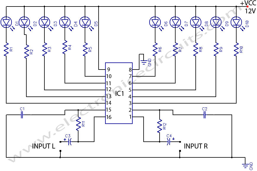
In a basic configuration, the audio signal is fed into the circuit, where it is compared to a reference voltage. The comparator IC evaluates the input signal levels and drives the LED indicators accordingly. When the audio signal exceeds the predetermined threshold, the comparator outputs a high signal, illuminating the corresponding LEDs. This allows users to visually monitor the audio levels, ensuring that they do not exceed optimal limits, which could lead to distortion or damage to the audio equipment.
The design can include multiple LEDs arranged in a bar graph format, providing a more detailed indication of the sound level. Each LED corresponds to a specific range of audio levels, enabling users to gauge the overall sound dynamics effectively. Additionally, the circuit can be enhanced with features such as adjustable sensitivity and hysteresis to prevent flickering of the LEDs during rapid changes in audio levels.
Power supply considerations are also essential in the design of the LED sound level indicator. The circuit typically operates on a low-voltage supply, commonly between 5V to 12V, ensuring compatibility with standard audio equipment. Proper biasing of the comparator and current-limiting resistors for the LEDs must be calculated to ensure reliable operation and longevity of the components.
Overall, the LED stereo sound level indicator is a valuable tool in audio applications, providing an intuitive and immediate visual representation of sound levels, which is crucial for both performance and equipment protection.LED STEREO SOUND LEVEL INDICATOR FOR AUDIO AMPLIFIER // Many circuits can be designed as level indicators by using a comparator IC or transistors but.. 🔗 External reference
Related Circuits
This circuit provides a simple visual indication of audio level signals, adaptable to various user requirements. It can be configured for different input levels, which can be adjusted using trimmer potentiometers TR1 (state) and TR2 (gain). The audio signals...
The IC1 is a 555 timer IC connected for astable operation. The clock pulses are fed to the IC2 via the 10K resistor. The IC2 is a 10-stage counter; output 6 (pin 5) is connected to RESET (pin 15),...
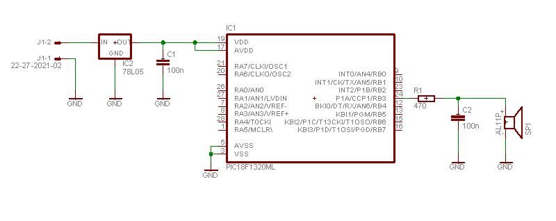
This project enables a PIC microcontroller to play audio PCM sounds using PWM modulation. Pulse-code modulation (PCM) is a digital representation of audio signals. The project utilizes a PIC microcontroller, which is programmed to generate audio signals through pulse-width modulation...
The circuit under discussion is a four-siren sound generator utilizing the UM3561 integrated circuit (IC), which is a low-power CMOS device. Four distinct sounds can be generated by activating switches S1, S2, and S3. This circuit is versatile and...
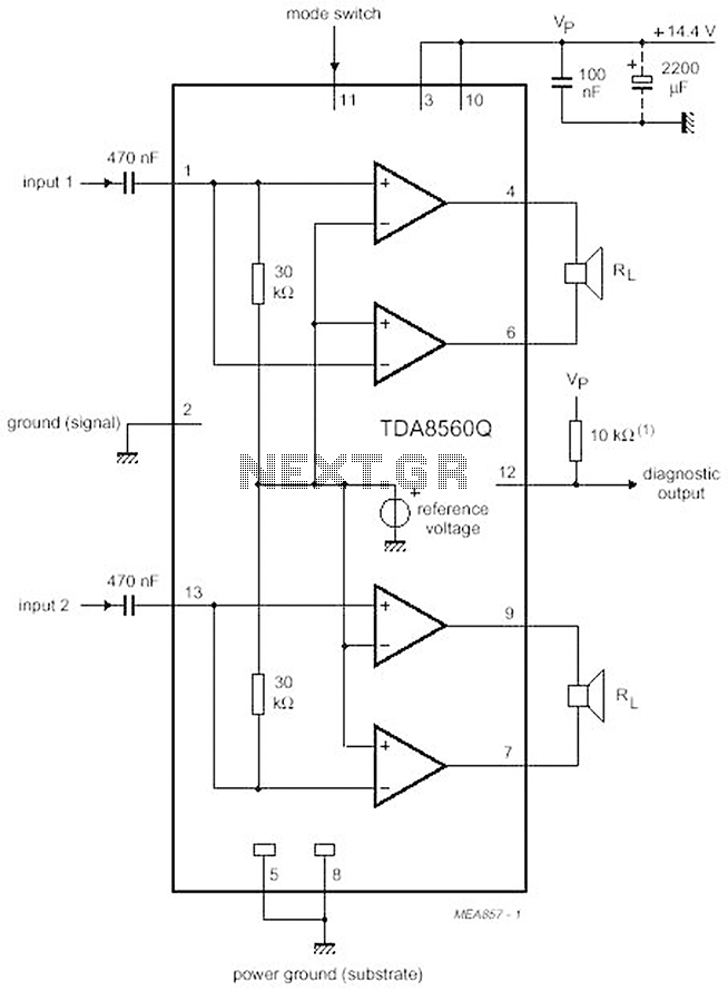
The proposed scheme is straightforward, requiring only a few external electronic components, making it suitable for car audio construction. The output power ranges from 2 to 4 Ohms, providing 2 x 30 W (with a maximum of 2 x...
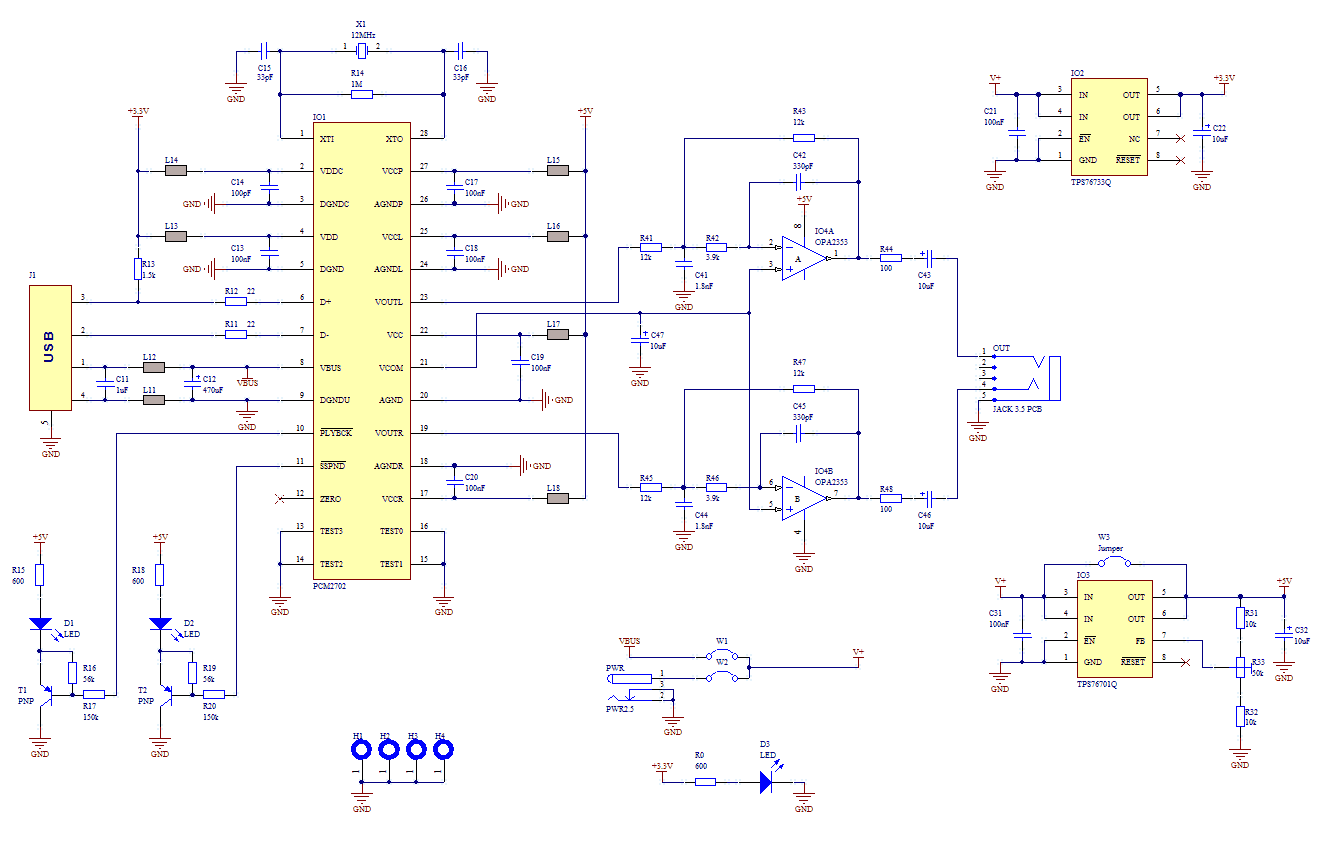
If you use great IC PCM2702 from BURR BROWN / Texas Instruments you can create a fully functional USB sound card. This sound card can be powered from USB port and has one stereo output. You don’t need to...