
Retriggerable Status Indicator Circuit
The circuit design focuses on extending the duration of a pulse generated by a device, ensuring that the RFC-1/B alarm system can effectively capture and respond to brief input signals. The use of the 74HC123A dual timer IC is advantageous, as it allows for the implementation of two independent pulse extender circuits within a single package, optimizing component usage and minimizing space requirements on the PCB.
The basic operation of the circuit involves the detection of input pulses at both rising and falling edges. When a pulse is detected, the 74HC123A initializes an output pulse that can be programmed to last several seconds, based on the selected resistor and capacitor values. The timing characteristics of the output pulse can be adjusted by changing R1 and C1, allowing for flexibility in various applications. The default configuration yields an output pulse of approximately 30 seconds, which is suitable for most scenarios where the RFC-1/B needs to ensure that it captures the status change.
The circuit also features a retriggerable timer function. This means that if a new input pulse is received while the output pulse is still active, the timer resets, providing an extended output duration. This capability is particularly useful in environments where frequent status changes are expected, ensuring that the alarm system remains responsive.
Both output configurations (high and low) offer versatility in interfacing with other components within the system. The ability to act as an inverter allows for integration into various logic configurations, enhancing the circuit's applicability in diverse electronic systems.
For power supply considerations, any regulated 5 VDC source is adequate. The inclusion of a low-cost switching power supply in the parts list simplifies implementation, while the optional 100 µF capacitor ensures stability under varying load conditions. The alternative schematic for a regulated 5 VDC power supply provides further options for users who may require a dedicated power source for the circuit.
Overall, this pulse extender circuit represents a robust solution for ensuring reliable monitoring of devices that generate short pulses, thereby enhancing the functionality and effectiveness of the RFC-1/B alarm system.It is sometimes necessary to monitor a device that generates a relatively short pulse to indicate a change of status. If the duration of the input signal is too short, the RFC-1/B may not have time to capture the pulse and respond appropriately.
The RFC-1/B alarm system scans one alarm channel every ten seconds. Depending on the number of alarms i n use, it may take several seconds for the alarm system to scan the channel and the input pulse may have expired. An effective solution is to extend the duration of the pulse to give the RFC-1/B time to sense the signal.
The circuits below do just that. One detects a pulse on the rising edge and the other detects a pulse on the falling edge. These circuits use a readily available IC, the 74HC123A, to sense the input pulse and generate an output pulse that can last several seconds. If a second input pulse arrives before the first output pulse has completed, the output signal timer restarts.
The 74HC123 is a dual timer IC. Only one timer is used for this pulse extender so two circuits can be built with one IC. The schematics show wiring for only one timer to simplify the drawing. Both circuits offer the option of either a high (+5 VDC) or low (0 VDC) output so these circuits can act as an inverter if necessary. Both outputs are shown in the schematics. The duration of the output signal depends on the choice of resistor R1 and capacitor C1. The values in the schematic produce an output pulse of about 30 seconds. Any regulated 5 VDC power supply should work. The parts list includes an inexpensive switching supply that will work. The optional 100 µF capacitor should be added if this switcher is used. Alternately there is a schematic for a regulated 5 VDC power supply shown below. 🔗 External reference
Related Circuits
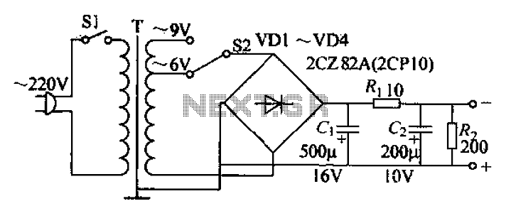
The adjustable current power supply circuit operates at 6V and 9V, utilizing a minimal number of components, which facilitates easy assembly. The circuit can deliver an adjustable output current of up to 100mA, serving as a suitable alternative to...
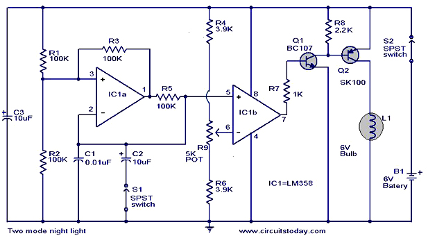
The operation and circuit diagram of a two-mode night light circuit are provided below. The two-mode night light circuit is designed to operate in two distinct lighting modes, typically offering a choice between a standard brightness setting and a dimmer,...
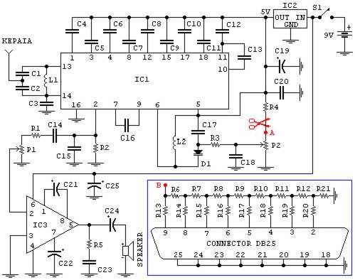
If familiar with programming languages such as C++, PASCAL, VISUAL BASIC, or DELPHI, it is possible to write a program that sends numbers from 0 to 255 through the parallel port (378 I) of a PC. This process checks...
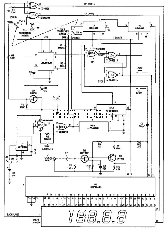
This is a schematic and block diagram of a 2-MHz frequency counter. It utilizes an LSI counter/display driver, an LCD readout, and several logic chips for timebase and timing pulse circuitry. Q2 and Q3 serve as a signal (input)...
This circuit is primarily designed to provide a microphone input for standard home stereo amplifiers. Utilizing a battery supply effectively eliminates the risk of low-frequency hum interference from mains power, simplifying the connection to the amplifier by removing the...
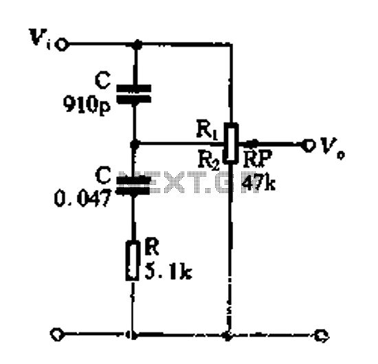
Figure 1-89 illustrates a loudness control circuit. A potentiometer is connected to ground, with 30% of the total resistance at the tap. When the slider arm is adjusted to the tap position, a midrange attenuation of 30 dB is...
Warning: include(partials/cookie-banner.php): Failed to open stream: Permission denied in /var/www/html/nextgr/view-circuit.php on line 713
Warning: include(): Failed opening 'partials/cookie-banner.php' for inclusion (include_path='.:/usr/share/php') in /var/www/html/nextgr/view-circuit.php on line 713