
Fastest Finger First project

The described circuit functions as a user interface for a quiz or game system, utilizing a series of 12V relays to control the output based on user inputs. Each user station is equipped with a button that connects to a common voltage source (Vcc) and a corresponding line (BNx) designated for that user. A light indicator is connected to another line (LTx) and grounded, providing visual feedback when the relay is activated.
To ensure reliable operation, the circuit employs a debounce mechanism using a monostable multivibrator (IC1A), which mitigates the effects of mechanical button bounce. When a button is pressed, the CAP line is driven high, and the monostable output triggers a low signal on the CK line for approximately 100 milliseconds. This ensures that only one button press is registered during that time frame. The use of 4013 RS flip-flops (IC2A) allows for the latching of the button states, enabling the corresponding relay to activate as long as the button remains pressed.
The system incorporates a reset feature to address potential power-up anomalies. A 100nF capacitor soldered across the RESET button generates a reset pulse upon power-up, establishing a defined initial state for the system. The design considers the use of either 5V or 12V relays, with the option to bypass current-limiting resistors when using 12V relays.
An active buzzer (if included) can provide auditory feedback, with its timing adjustable via a 10K trimmer (R32) to set the duration of the sound. The circuit's layout is designed for ease of assembly on VeroBoard, with clear guidance on component placement to facilitate accurate construction.
The wiring between the control unit and user stations is standardized, utilizing a 10-core cable that carries power and signal lines, ensuring that the system remains organized and functional. The arrangement of user connectors at opposite ends of the PCB allows for flexibility in user placement, accommodating various team configurations. Overall, this circuit design provides a robust solution for interactive quiz systems, ensuring fair play and clear communication among users.If 12V relays are used, you can replace the 180R resistors R7,R9,R14,R16,R20,R22,R26 and R28 with a wire link (the resistors are only there to limit current if you use 5V relays, of which I had a load in my parts bin). If the system doesn't reset cleanly on power-up (several lights may come on or the relays may chatter), just solder a 100nF capacitor across the RESET button.
This will cause a reset pulse to be generated at power-up so that the initial state is defined. If you don't want the nice "beep", leave out the NE555 (IC6) and its associated components. Note that the buzzer needs to be an "active" one, i.e. one that includes its own drive electronics such that simply applying a DC voltage makes it sound. If you want to use less or more button/light positions just omit/include some of the replicated logic (it's fairly clear from the schematic above). Note the pin/contact layout of the relays used. Not all DPDT DIL relays use the same layout - be careful! R32, the 10K trimmer, is used to vary the length of the on time of the buzzer between about 0.25 and 1 second - I found that about 0.5 seconds was quite enough.
The prototype was built on VeroBoard (StripBoard in the USA). If you use roughly the same positions for components as shown in the board layout above, you won't go far wrong. How does it work? Each user station has a button connected between Vcc and its BNx line, and a 12V light connected between its LTx line and GND.
For each user, a copy of the circuit below is on the main circuit board. This controls handling of the user's button and driving the output relay.
When any user presses their button, the CAP line will go high. As buttons always 'bounce', there will be a whole raft of pulses in the first few milliseconds before the contacts in the button settle down. IC1A is configured as a monostable that drives the CK line - this will go low for about 100mS when the monostable is triggered.
Remember that 4013 RS flip-flops are positive edge triggered, so when IC1A times out, the CK line will go high. If any button is still pressed, the BNx line will be latched through to its Q output (see IC2A above), turning on its relay.
At the same time, IC1B will latch the CAP line to its Q output. If any button is pressed, this will cause IC1A's RESET input to go high, forcing the CK line low regardless of any other pulses on the CAP line, thus debarring other users who may subsequently press their buttons, i.e. IC1A's monostable cannot be fired again until the RESET button is pressed. This mechanism ignores noise spikes and bounces on any button line, and completely blocks other users once the first user has pressed their button.
The only way one or more outputs may be triggered at the same time is if the users press their buttons within IC1A's timeout period (about 100mS), thus indicating a draw. Because of the high noise immunity of the circuit, you can use multi-core cable to connect the control unit to the users' boxes.
Each box requires 4 wires - two of these, GND and Vcc (+12VDC) are common to all boxes; the other two are the users' BNx and LTx lines. The BNx line needs to be connected via a push-button to the Vcc line, and some 12V MES bulbs (or similar) need to be connected between the LTx line and GND.
As these sorts of systems are generally used by two teams of up to 4 users , I placed the two user connectors at each end of the PCB. These are standard IDC 2x5 box headers on a 0.1" matrix. I then used 10-core cable to each group of 4 user boxes, with the Vcc and GND wires being daisy-chained through and dropping out a pair of BNx and LTx lines in each box.
The cable from the control unit to the first box was 2M long, and the cable between each box in a chain was 1M. The quiz master can then sit at the control box between the teams. It should be noted that all users are equal - the system doesn't differentiate between users, so the split is for typical conveniance only; 8 teams of 1 user or 4 teams of two are equally valid combinations.
Alternatively, you can easily add more users (see below) to have 2 teams of 10 etc.
Related Circuits
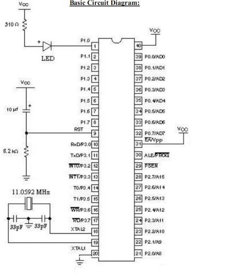
Microcontrollers and Microprocessors - The 8051 Projects Page! Discover comprehensive information on 8051 projects here. Everything you wanted to know about 8051 projects is available. The 8051 microcontroller, developed by Intel in the 1980s, is a widely used microcontroller in...
This device has been designed as a demonstration application of an expandable system of modules for constructing mobile robots, adhering to the standards discussed in the Society of Robots forum. These modules can interconnect using an I2C bus, and...
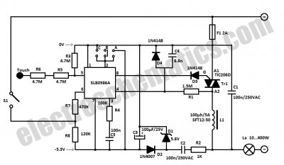
This light dimmer control features active timing capacitor reset or AC line zero-crossing synchronization. The 13 additional components are common and cost less than $2. Performance at the low end is exceptionally smooth and snap-free, even better than the...
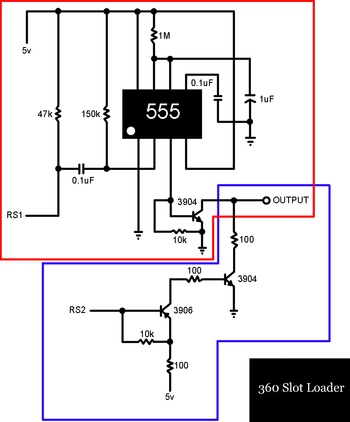
A slot-loading Xbox 360 features a mechanism similar to that of a MacBook, where a CD or DVD is inserted into a thin auto-loading slot rather than using a button to extend a mechanical tray. In contrast, the Xbox...
The Atmega 8535 Color Conversion to Frequency project utilizes instrumentation technology to recognize colors, also known as a color sensor, which is essential in various industrial applications. This sensor has multiple uses, ranging from the paint industry to satellite...
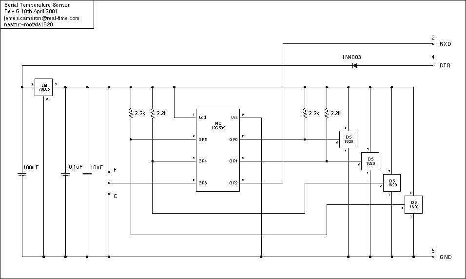
Just a handful of components builds an 8-pin microcontroller based circuit for temperature logging via a serial port; small, fast, and acceptably accurate. More: provides real-time data to your computer via serial port, interfaces up to four DS1820 temperature...