
Module Project Template

The described module serves as an integral component of a modular robotic system, enabling communication and control among various modules through standardized interfaces. The I2C bus facilitates a multi-master, multi-slave configuration, allowing multiple devices to communicate without direct connections. The master module's UART interface provides versatility in connecting to external devices, enhancing the system's capability to interact with computers or other peripherals.
The ATmega8 microcontroller, with its accessible I/O pins, supports diverse applications, making it suitable for both prototyping and development. The firmware's structure allows for customization, enabling users to tailor the module's functionality to specific applications. The requirement for unique addressing ensures that data packets are routed correctly within the network, preventing conflicts and ensuring reliable communication.
The inclusion of a level shifter, such as the MAX232, is crucial for interfacing with standard RS-232 serial communication protocols, facilitating effective data exchange between the microcontroller and external devices. The emphasis on programming skills highlights the module's complexity and suitability for users with prior experience in microcontroller projects.
Overall, this module exemplifies a robust platform for developing and testing mobile robotic applications, providing essential features for communication, control, and customization, while also serving as a valuable learning tool for advanced users in the field of electronics and robotics.This device has been designed as an example application of an expandable system of modules for building mobile robots following the standards set out in the discussion on the Society Of Robots forum. These modules can be connected to each other using an i2c bus and Master modules like this one can also be connected via a UART to a wide variety of
equipment. (eg, PC serial and USB ports. ) This particular module acts as a Master node on the i2c bus and has one UART which can be connected to a PC serial port or USB port with the addition of a simple level shifter. With a little configuration and editing of the local_function in main. c the logic of the AVR ATmega8 I/O pins can be changed on the local module or any similar module connected to the i2c bus.
All available I/O on the ATmega8 has been brought out to header pins making this a good platform for testing firmware for new module designs before thy have been built. This is *not* recommended as your first microcontroller project though. The additional complexity of an i2c networked microcontroller project puts it beyond the scope of novice builders.
If on the other hand you have sucsessfuly built and programmed a microcontroller board in the past this module (and the other modules to come in the series) may be just what you are looking for. Welcome. You will need to be able to read a circuit diagram, source and purchase the parts, either make your own PCB or use some alternative (eg.
stripboard), compile and upload the firmware to the microcontroller. If you have not done *all* of these tasks at some point in the past we recommend a simpler project, or at least wait until there a few finished module designs out there. As this is a template module rather than a finished one you will also have to do a little C programing to do anything useful with it.
The hard work of writing the i2c and UART code has been already done for you though. I have successfully created these PCBs using the "Toner Transfer" method and the Eagle PCB is optimised for home PCB manufacture rather than by professional board houses. The firmware for this project requires avr-gcc and avr-libc (a C-library for the AVR controller). Please read the instructions at for how to install the GNU toolchain (avr-gcc, assembler, linker etc.
) and avr-libc. Once you have the GNU toolchain for AVR microcontrollers installed, you can run "make" in the subdirectory "firmware". You may have to edit the Makefile to use your preferred downloader. Each module on the network must have unique addresses for all interfaces. For this module that means editing "main. h" and giving LOCAL_ADDR and UART_ADDR1 unique hex addresses between 0x02 and 0xFF. These addresses must be even numbers. For initial testing one module on the bus should have a UART level shifter such as a MAX232 connected to the ATmega8`s UART pins (header SV3).
This level shifter should be connected to a PCs serial port running terminal emulation software (eg. hyperterminal). Packets can then be typed directly into the terminal emulation software to send commands to various modules.
~B004 (Optional) If the packet arrives at a master node and ~B exists and is not equal to 000 then the master node (in this example 002) will consult a lookup table to see which UART (or other port) to send the packet out of. In this case the packet will be sent to the UART. Result: The packet "~A002~S~0100~1101~2102" arrives at the module with the i2c address 002. Some programing of the Firmware of this module must take place to do something useful with the bytes contained in data[0], data[1] and data[2] Result: Three characters are requested from the module with the i2c address 002.
Providing the programing of the Firmware of this module has allowed for it, th 🔗 External reference
Related Circuits
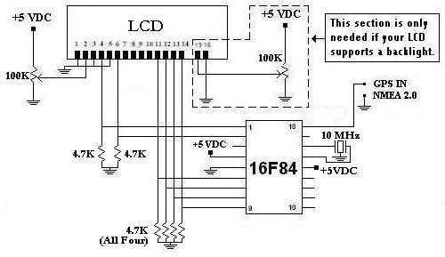
This is a project that I started back late 2003 when I just starting to learn PIC programming. I wanted to building something that actually did something useful. This project is based on a PIC16F84. I actually came up...
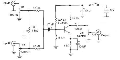
This audio mixer circuit diagram electronic project is designed using a few common electronic components. The audio mixer circuit project has two input channels. The input signal can be independently controlled using the R1 and R2 variable resistors. The...

This audio noise filter circuit is a bandpass filter designed for the audio frequency range. It effectively filters out unwanted signals that fall outside the audio frequencies. The circuit consists of two filters: a low-pass filter and a high-pass...
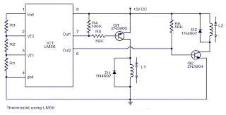
The values of the LM56 thermostat project circuit diagram for resistors R1, R2, and R3 at the travel points VT1 and VT2 can be determined using the following equations. This electronic circuit thermostat with the IC LM56 serves as...
The vehicle is a 2005 Pontiac GTO equipped with a 6.0L engine and a 6-speed manual transmission. The factory headlights, which utilize H11 low-beam projectors, have been found to provide inadequate illumination, prompting a retrofit. The plan includes mounting...

This varactorless high-frequency modulator electronic project must be powered by a simple DC 3-volt power source, such as a 3-volt battery. Traditionally, high-frequency oscillators are frequency-modulated using a varactor. However, varactors typically require a significant voltage change to achieve...