
Fax to Modem interface

The described circuit is designed for integration within a compact plastic enclosure, featuring telephone connectors on both ends to facilitate direct connection to telephone lines. The operating current for this circuit is approximately 10-20 mA, indicating a low power requirement. For applications where the circuit is not continuously in use, battery power is recommended to enhance portability and reduce power consumption. Alternatively, a small wall transformer can be employed, provided it is a regulated model to ensure minimal output noise. Unregulated transformers may introduce unwanted noise, typically manifesting as a 50/60 Hz hum, which can adversely affect signal quality.
A critical component in the circuit is the 680-ohm resistor, which serves to limit the voltage from a 12V source, ensuring that the power supplied to the telephone electronics remains within safe operating limits. However, this resistor can lead to an impedance mismatch with the telephone line, potentially degrading performance. To mitigate this issue, a capacitor can be introduced in parallel with the 680-ohm resistor. The capacitor effectively allows the circuit to present itself as a low-impedance path for voice frequencies, thereby minimizing the effects of the impedance mismatch.
Furthermore, a 22-ohm resistor is suggested in series with the capacitor to control inrush current when the connected equipment is activated. This precaution helps protect sensitive electronic components from potential damage due to sudden current spikes. It is important to note that for standard FAX to modem applications, this modification may not be necessary, as most equipment is designed to handle the impedance mismatches created by the original circuit configuration without adverse effects. This design consideration ensures that the circuit maintains compatibility with typical telecommunication devices while optimizing performance.The circuit can be easily built to a small plastic box with telephone connectors in both ends. The circuit takes about 10-20 mA current, so if the circuit is not in use all the time it is best to use batteries. You can also use small wall transformer to power the circuit. Remeber to take a wall transformer which gives good quality output (regulated model preferred), because if the wall transformer gives out noise, it can be hard on the line (usully you hear 50/60 Hz buzzing).
The 680 ohm resistor (used for limiting the power from 12V source to safe value for telephone electornics) causes some problems because it causes imedance mismatch to the telephone line. If this causes problems, you can add a capacitor to the circuit which makes sure that the circuit apperas to be like piece of wire in voice frequencies you can avoid mismatch caused by that 680 ohm resistor.
I added a 22 ohm resistor in series with the capacitor to limit the surge current which appears when the equipments go on-line. For normal FAX to modem usage this modification should not be necessary because equipments should be able to cope with those impedance mismatches the original circuit causes.
🔗 External reference
Related Circuits
This is a simple 220V power interface circuit. This circuit is used as an interface for monitoring electrical devices and equipment using a computer. The 220V power interface circuit serves as a critical connection point between high-voltage electrical systems and...
BR Communications, which later merged with TCI to become TCI/BR and was subsequently acquired by Dielectric Inc., produces a series of chirp sounder transmitters and receivers. One notable feature of the Chirp Sounder system is the narrow shift order...
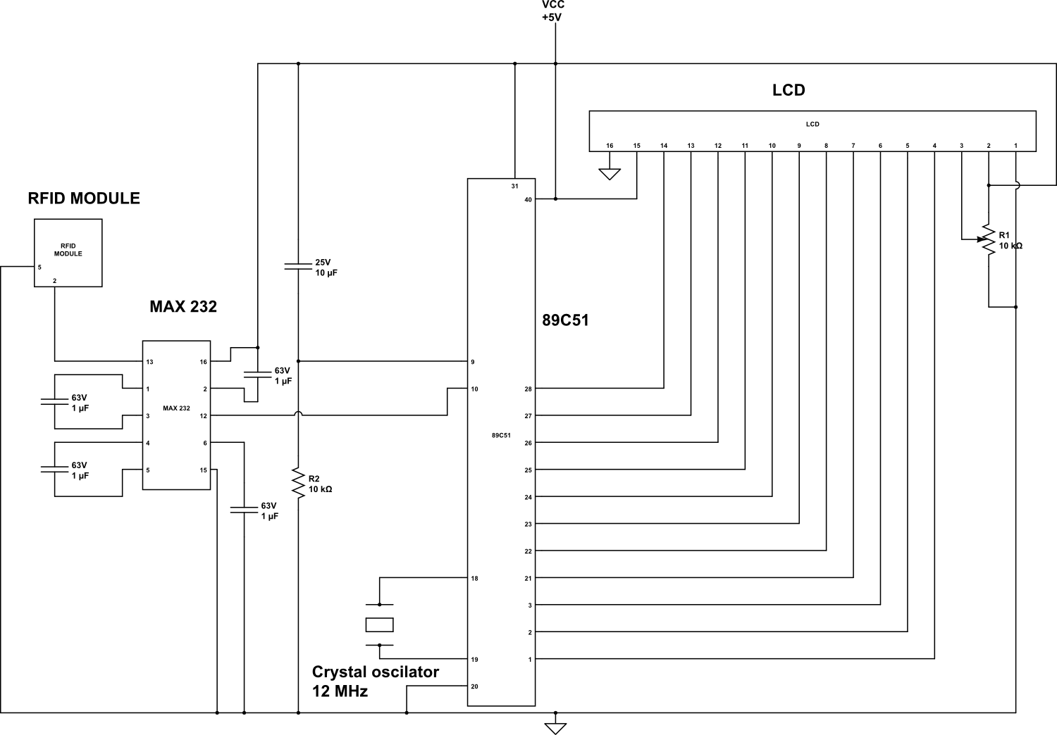
An RFID (Radio-frequency identification and detection) reader is a device used to communicate with RFID tags by receiving and transmitting signals. These signals utilize radio waves for wireless communication. RFID tags are applied to products, individuals, or animals for...
This self powered interface circuit electrically isolates the TxD and RxD lines from the PC serial port and protects the PC from direct connection to hazardous voltages. The isolator is intended to provide electrical isolation between a computer and...
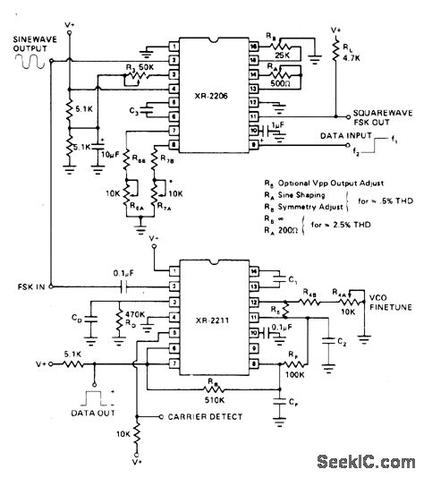
The values indicated are for a 13 kHz bandwidth, with 1070 Hz for the mark signal and 1270 Hz for the space signal. This utilizes the Exar XR-2206 function generator and the XR-2211 FSK demodulator. The report outlines the...

The FTDI DLP-USB245M is a USB-to FIFO interface module that simplifies the control of multiple stepper motors by a PC. The FTDI DLP-USB245M module is designed to facilitate communication between a PC and various electronic devices, specifically enabling the control...