
220V Power Line Interface

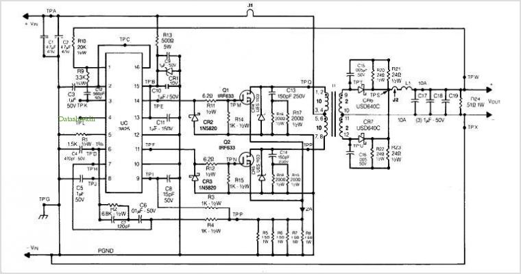
The 220V power interface circuit serves as a critical connection point between high-voltage electrical systems and low-voltage monitoring equipment, such as a computer. The circuit typically includes essential components such as a step-down transformer, which reduces the high voltage from 220V AC to a safer level suitable for monitoring purposes.
Additionally, the circuit may incorporate an opto-isolator to provide electrical isolation between the high-voltage side and the low-voltage monitoring side, ensuring safety and protecting sensitive components from voltage spikes.
A rectifier circuit, often composed of diodes, may be included to convert the AC voltage to a DC voltage, allowing for easier processing by the computer. Capacitors can be used for filtering to smooth out the rectified voltage, providing a stable power supply for the monitoring system.
Furthermore, the circuit can integrate a microcontroller or an analog-to-digital converter (ADC) to facilitate the acquisition of voltage and current measurements from the connected devices. This data can be relayed to the computer for monitoring, analysis, and control purposes, enabling users to track the performance of electrical devices and optimize their operation.
Overall, this 220V power interface circuit is a fundamental component in automated monitoring systems, enhancing the ability to manage and analyze electrical equipment efficiently.This is a simple 220V power interface circuit. This circuit used as interface for monitoring electric devices and equipments using a computer. The circuit only. 🔗 External reference
Related Circuits
The U2745B is a Phase-Locked Loop (PLL) transmitter integrated circuit (IC) designed specifically for low-cost radio frequency (RF) data transmission systems, supporting data rates up to 20 kBaud. It operates within a transmitting frequency range of 310 MHz to...
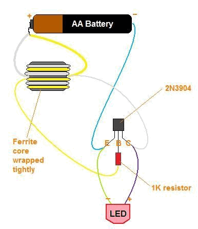
The title contains numerous words because this instructable integrates various concepts from multiple sources. The primary idea originated from Robomaniac's Desktop Energy Seed Lamp, combined with Witch's Growing Plants with LED Lights instructable and various wick gardening planters. The...
The two circuits demonstrate the operation of opening a relay contact shortly after the ignition or light switch is turned off. The capacitor becomes charged, and the relay remains closed until the voltage at the diode anode reaches 12...
This is a high-quality stabilized power supply circuit diagram. The output voltage can be adjusted from 0 volts to 30 volts DC, and the current output value can be adjusted from 0.002 A to 3 A. The circuit begins...
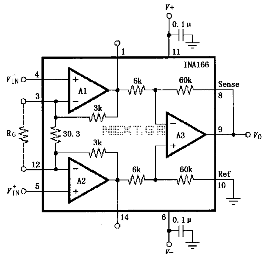
The basic connection circuit for the INA166 includes signal and power connections. A 0.1 µF tantalum capacitor should be used for filtering the chip's power supply terminal, and the PCB layout should be designed to position this capacitor as...

This is a single-zone alarm system featuring independently adjustable Exit, Entry, and Siren Cut-Off timers. It is compatible with standard normally-closed input devices such as magnetic-reed contacts, foil tape, and passive infrared sensors (PIRs). A mains power supply can...