
how to interface rfid with 8051

The RFID reader system described operates as a complete solution for identifying and tracking objects using RFID technology. The AT89C51 microcontroller serves as the central processing unit, managing the data flow from the RFID reader to the user interface, which is presented on an LCD display. The RFID reader emits radio waves that energize the RFID tags within its detection range, allowing the tags to transmit their unique serial numbers back to the reader.
The use of the ICMAX232 level converter is critical for ensuring compatibility between the RFID reader's output and the AT89C51's input requirements. The MAX232 converts the signal levels from the RFID reader, which typically operates at TTL levels, to the voltage levels required by the microcontroller. This conversion is essential for reliable communication, as mismatched voltage levels can lead to data corruption or communication failure.
In the schematic, the RFID reader's output is connected to the R1IN pin of the MAX232, which processes the incoming serial data. The output from the MAX232 (R1OUT) is then sent to the RxD pin of the AT89C51, allowing the microcontroller to read the incoming data. The microcontroller is programmed to interpret the serial data, extract the unique serial number of the RFID tag, and display it on the LCD interface for user feedback.
The choice of a low-frequency RFID system, specifically the 125 kHz tags, is suitable for applications requiring short-range communication, such as access control or inventory management. The system's range of approximately 10 cm is adequate for many practical scenarios, ensuring that the RFID tags can be read reliably without interference from nearby objects. Overall, this RFID reader system exemplifies a practical application of microcontroller interfacing with RFID technology, demonstrating the integration of hardware components and software programming to achieve a functional electronic system.An RFID(Radio-frequency identification and detection) reader is a device which is used to communicate with RFID tags by receiving and transmitting signals. These signals use radio waves for wireless communication. RFID tag is applied to products, individuals or animals to identify and track them. The identification is done through a unique serial nu mber. This topic covers the interfacing of a passive RFID system withAT89C51. The code of RFID tag is also displayed on anLCDinterface. The free source code for the program isavailablein C. AnRFIDmodule basically consists of two parts, namely, a tag and a reader. A typical RFID system consists of an antenna, a transceiver and a transponder (RF tag). The radio frequency is read by the transceiver and the information is transferred to a device for further processing. The information (the unique serial number) to be transmitted is stored in the RF tag or transponder. The transponder contains a chip and an antenna mounted on a substrate. The chip transmits the relevant information through antenna. The antenna also receives the electromagnetic waves sent by the RFID reader. Different RFID tags work on different frequencies. Here low frequency, 125 kHz, RFID tags have been used. These tags work within a range of 10 cm. When an RFID tag comes in this range, the reader detects it and sends a unique code of the tag serially.
This serial code, consisting of 12 bytes, is received by the microcontroller. A serial level converter is required forAT89C51to receive these serial signals. ICMAX232has been used for this purpose to interface the RFID reader with microcontroller. The circuit connections are as follows: Receiver1 (R1) of MAX232 has been used for the serial communication. The receiver pin of RFID reader is connected to R1IN (pin13) of MAX232. R1OUT (pin 12) of MAX232 is connected to RxD (P3. 0) of microcontroller. 🔗 External reference
Related Circuits
I designed a simple sinewave generator based on a Analog Devices AD9832 chip. It will generate a sinewave from 0.005 to 12 MHz in 0.005 Hz steps. That's pretty good, and definitely good enough for me! But while waiting...
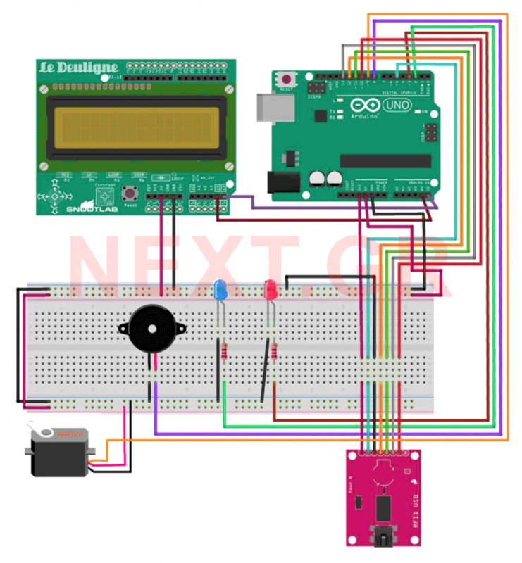
This project aims to develop a security system suitable for business environments or for simple home use. The system utilizes an Arduino Uno microcontroller in conjunction with RFID (Radio Frequency Identification) technology, enabling wireless user identification. Only registered users...
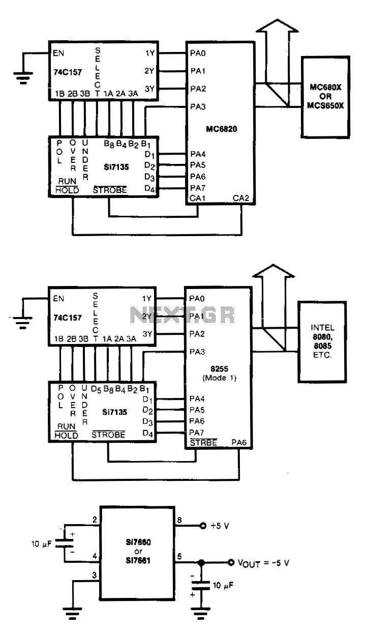
Circuits to interlace the Si7135 directly with two popular microprocessors are shown in Figs. 18-2a and b. The 8080/8048 and the MC6800 families with 8-bit words need to have polarity, overrange, and underrange multiplexed onto the digit 5 word....
This project involves controlling an AVR microcontroller (MCU) using Visual Basic 6. The applications of this circuit are numerous, enabling the creation of various devices that require control from a Personal Computer (PC) or any circuit that collects data...
Watching the time on a mobile phone in the dark can cause discomfort due to the strong contrast between bright and dark backlighting. To address this issue, the "ICON" model is utilized, which operates in standby mode with a...
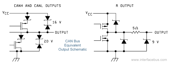
The Controller Area Network (CAN) Interface is a balanced (differential) two-wire interface that operates over Shielded Twisted Pair (STP), Unshielded Twisted Pair (UTP), or ribbon cable. Each node in the network utilizes a male 9-pin D connector. The bit...