
Features and Power Control Circuit

The circuit design incorporates a triac (TR1), which serves as the primary switching element, providing efficient control of AC power. The use of a potentiometer (R1) allows for fine-tuning of the output, enabling the user to adjust power levels according to specific requirements. The relay (RLY1) plays a crucial role in controlling the power flow to the load, ensuring that the system operates safely and reliably. The integration of meters for voltage and current measurement enhances the functionality of the circuit, allowing for real-time monitoring of performance and facilitating troubleshooting.
The cooling strategy, including the use of a fan and heat sink, is essential for maintaining optimal operating conditions, particularly given the potential for heat generation during high-power operation. The design's emphasis on modularity and accessibility through the circuit board layout promotes ease of maintenance and adaptability for future enhancements or modifications.
Overall, this circuit exemplifies a practical solution for power control applications, combining simplicity, reliability, and versatility, making it suitable for a range of electronic projects and devices.The hardest part of the build was to find and / or design a circuit that could handle the load and still stay with in my budget. This little circuit does both. It varies the power output with one potentiometer (variable resistor) R1. R1 is a panel-mount pot with a shaft for a knob. It varies the power by synchronous triggering across the triac. On the triac TR1, terminal T1 is input, terminal T2 is output and G is the gate. All the parts were readily available form my local electronic supply store and built on a point to point prototype circuit board. This is a simple but a reliable circuit which will handle 15 Amps but in my unit it only has to about 4 Amps since I am controlling the primary windings of the transformer.
On a side note, this circuit can be adapted to numerous other applications where controlling power is a requirement as in a lamp dimmer or putting a variable speed feature on an AC motor like a drill. As soon as SW1 is turned on, L1 and FAN1 come on. I wanted to do all the switching and control on the primary side of T1. Even though the voltage is higher (120VAC), the current would be much lower. The circuit is switching the incoming AC into the power control circuit thru relay RLY1. In turn, RLY1 is being controlled by SW2. The current draw of RLY1 is very small so this allows SW2 to be compact allowing mounting almost anywhere as in my pistol like soldering gun (carbon rod holder).
I mounted SW2 in the trigger position eliminating the need for a foot switch. With my tweezer set up, the floor switch is still employed. L2 comes on with RLY1 and is mounted to the front panel. Voltage is fed from the power control circuit to T1. The highest current draw that the power control circuit with RLY1, FAN1 and T1 at full power is approximately 4 Amps. Since all this is passing thru RLY1, RLY1 should be rated for at least 10A. I rated F1 at 4. 5A. On the output of T1, a voltage meter and an amp meter are installed. This gives me a good idea of the wattage output for any soldering operation. For instance, if I read 2 volts and 20 amps, using Ohm`s law: METER2 (volt meter) is connected across T1 while METER1 (amp meter) is connected to T2 (current transformer).
T2 was constructed from four 2 steel washers welded together to make one thick doughnut core. Light gauge wire was wrapped thru the hole and around the outside. I wrapped about 60 turns of the wire and connected each end to the meter terminals. The output of T1 was also wrapped about 6 times thru the hole. This matched the transformer to METER1 which brought it very close to the actual output as tested by my Fluke meter. With power set to MAX, I can pull about 50 amps @ 4 volts which is exactly 200 watts! Interestingly enough the primary side of T1, draws about 4 amps on MAX. So again using Ohm`s law, this comes to 480 watts (120volts x 4amps). With 480 watts going in and only 200 watts coming out the rest must be loss. A lot of this loss is dissipated by heat so that`s why I found it important to keep the unit as cool as possible with the cooling fan and rate it at 25% duty cycle.
For every minute of operation I let it rest for four all though a typical cycle only lasts a few seconds. I also have a good size heat sink on TR1. Also of note, T1 has a center tap. If the center tap is used, the output drops to about 6 VAC. One item I am meaning to test is the operation on the lower voltage to find out if there is a performance gain.
This picture and schematic 3 show how I used the circuit board as a central connection point and colour coded the wiring. All external devices plug into the board. This will allow easy removal and service of the board and the outboard components. This feature also permits easy modifications! And this is all the components put together. I made a false bottom plate so every time I wanted to change the internal configuration, it was just a matter of replacing it rat
🔗 External reference
Related Circuits
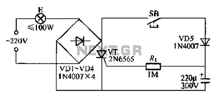
This circuit is a simple connection delay lamp circuit. When the lights are turned on and the switch is pressed, the power supply is activated. The capacitor charges rapidly, causing the thyristor (VT) to open, which in turn lights...

A 750mW bridge-tied load audio amplifier circuit utilizing the LM4065 amplifier is presented below. The LM4865 is available in an 8-pin SO package and an 8-pin mini SMD package. The power supply voltage (VDD) ranges from 2.7V to 5.5V,...
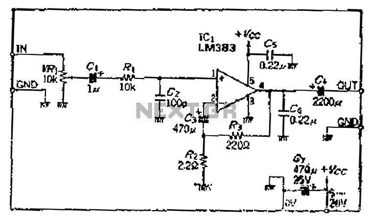
A closed-loop amplification circuit is designed to achieve a magnification of 100 times (40 dB). To ensure stable operation, particularly with high input signals, a variable resistor (VRi) is incorporated in the secondary circuit for attenuation. The feedback resistor...
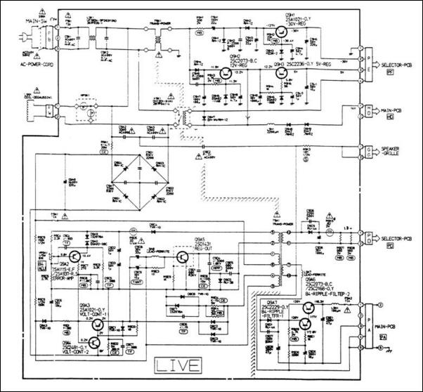
A 12V switching power supply schematic has been observed to generate significant heat, which has prompted discussions among users in prominent forums, such as dp. The 12V switching power supply is a crucial component in various electronic applications, providing...
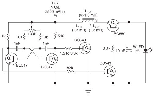
This single white LED torch can be housed in an empty glue stick tube and has a long rechargeable battery life. The proposed circuit design features a compact LED torch that utilizes a single white LED as the primary light...
This circuit is a low-frequency Wien bridge sinusoidal oscillator designed for the audio range, characterized by very low distortion, making it suitable for testing various audio equipment. The circuit has undergone thorough testing, and a printed circuit board (PCB)...