
Oscillator circuit

This Wien bridge oscillator circuit is particularly valuable for audio testing applications due to its ability to generate stable sine wave signals with minimal distortion. The low distortion characteristic is critical in ensuring accurate testing and evaluation of audio equipment, as it allows for a clean signal that does not introduce additional artifacts.
The operation of the Wien bridge oscillator relies on the precise balance of resistive and capacitive components, which are adjustable via the rotary switch. This flexibility in frequency selection allows the user to test audio equipment across a range of frequencies, from bass to treble. The use of the uA747 integrated circuit simplifies the design while providing reliable performance. The dual op-amp configuration allows for efficient signal generation and amplification, ensuring that the output maintains integrity even when driving varying loads.
The incorporation of a FET transistor in the design serves a dual purpose: it regulates the output amplitude and helps maintain a consistent output across the selected frequency range. This feature is particularly advantageous when testing equipment that may have varying input sensitivities.
The PCB design is compact and thoughtfully laid out to facilitate easy assembly of the circuit components. This professional-grade PCB, along with the complete kit, provides an accessible solution for engineers and hobbyists looking to build their own Wien bridge oscillator. The availability of a pre-manufactured board significantly reduces assembly time and potential errors associated with manual circuit construction.
In summary, this low-frequency Wien bridge sinusoidal oscillator represents a robust solution for audio testing, combining high performance with user-friendly features. Its design and component selection reflect a careful consideration of the needs of audio engineers, making it a valuable tool in the field.It is a low frequency Wiew bridge sinusoidal oscillator for the audio range with very low distortion, useful to test a variety of audio equipments. The circuit has been fully tested and a PCB circuit board is available to easily mount all components.
The circuit uses only one integrated circuit, some passive components and is able to provide more than 15 V peak-to-peak or 5V RMS with a distortion less than 0. 1%. In addition it uses a FET transistor to control the output amplitude and maintain it flat across the frequency range. The circuit has been designed to use a single uA747 chip that includes two op-amps inside. The first op-amp (U1A) is configured as a Wiew bridge oscillator with very low distortion. The rotary switch SW1A, B provides the connection to six different resistances and capacitor couples to cover six different audio frequencies.
The operating frequency can be easily changed using the formula in 1. The second op-amp U1B is used as an inverting output amplifier to decouple de circuit from the load and increase the output signal up to 15 Volt peak-to-peak. For those that would like to build the Wiev bridge oscillator, a professional made PCB and a complete kit with all parts is available.
The PCB is small and able to accommodate all components. 🔗 External reference
Related Circuits
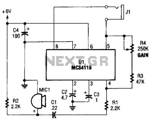
The first amplifier circuit is a bird phone. In this circuit, the electret microphone (MIC1) is mounted in the neck of a large plastic funnel. The amplifier, built around an MC34119, is then placed outside of the funnel with...
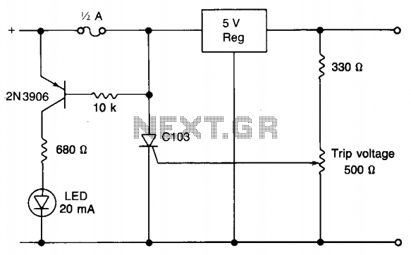
When utilizing a regulated power supply to decrease voltage, there exists a risk of component failure within the supply, potentially resulting in damage to connected equipment. While a fuse can provide protection against excessive current draw, it may not...
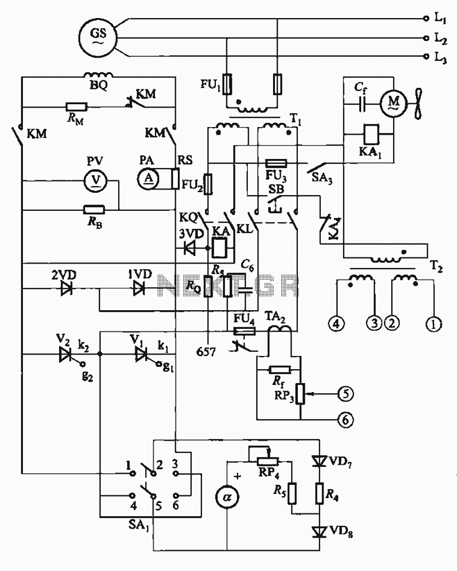
The FKL-32 type automatic thyristor excitation device is designed for synchronous generators with a terminal voltage of 400V and a capacity of 500kW or below. It is used for the automatic adjustment of excitation. The FKL-32 automatic thyristor excitation device...
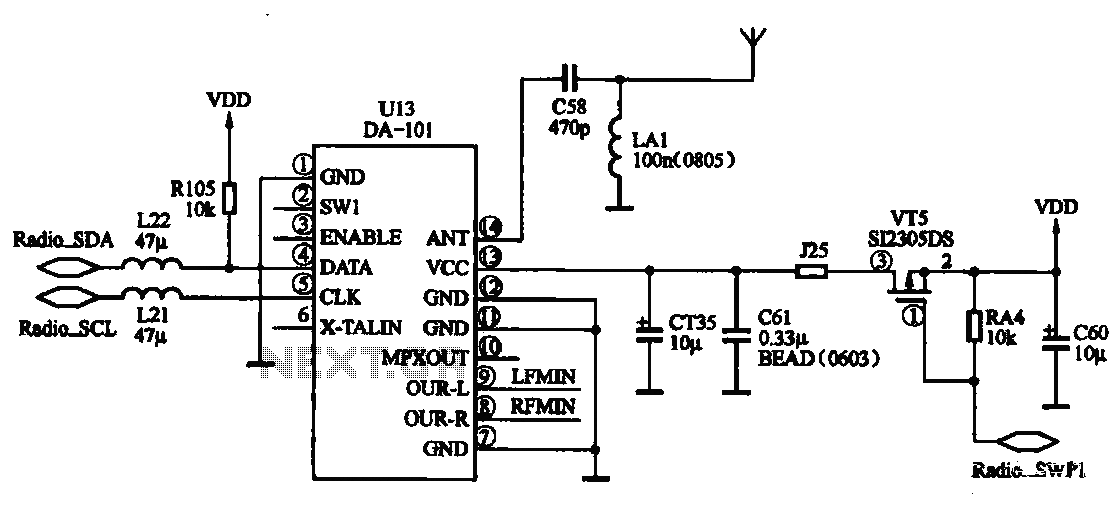
FM radio chip circuits operate differently, as illustrated by the DA-101 chip FM radio circuit. In this configuration, the FM radio broadcast program is received through the headset jack, which functions as an antenna. The signal captured by the...
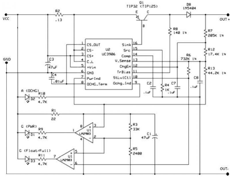
The UC3906 battery charger circuit controller includes all necessary circuitry to manage the charge and hold cycles for sealed lead-acid batteries. This circuit is specifically designed to deliver the appropriate charging voltage and current based on the battery's temperature...
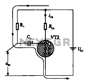
When VRI is off, 0 [2 is activated, allowing current to flow through RJ and Ci. When VT1 conducts, charging of C1 begins, causing it to discharge. This results in an inverting charge on C1, making the voltage positive,...