Fog Lamp Sensor Circuit
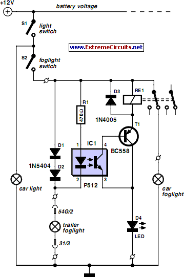
For several years, a rear fog lamp has been mandatory for trailers and caravans to enhance visibility in foggy conditions. When the fog lamp is activated, the fog lamp of the towing vehicle must be turned off to prevent irritating reflections. To achieve this, a mechanical switch is integrated into the 13-way female connector to disable the fog lamp of the towing vehicle and activate the fog lamp of the trailer or caravan. For users with a 7-way connector, this switching can also be accomplished electronically using the circuit outlined here. In this circuit, a type P521 optocoupler detects whether the fog lamp of the trailer or caravan is connected. If the fog lamp is activated in the towing vehicle, current flows through the caravan fog lamp via diodes D1 and D2. This causes the LED in the optocoupler to illuminate, resulting in the conduction of the phototransistor, which powers the relay through transistor T1. The relay then turns off the fog lamp of the towing vehicle. This compact circuit can be easily constructed on a small piece of perforated circuit board and installed near the rear lamp fitting of the towing vehicle.
The electronic schematic described involves a straightforward yet effective method for managing the operation of fog lamps in trailers and towing vehicles. The circuit utilizes a P521 optocoupler as a key component, which serves to electrically isolate the control signals while allowing for the detection of the fog lamp status.
The operation begins when the fog lamp in the towing vehicle is turned on. Current flows through the diodes D1 and D2, which are configured to protect the circuit and ensure proper signal flow. These diodes also prevent backflow of current, thus safeguarding the components. The illumination of the LED within the optocoupler indicates that the fog lamp is activated. This light triggers the phototransistor inside the optocoupler to enter a conductive state, allowing current to flow to transistor T1.
Transistor T1 acts as a switch for the relay, which is designed to handle higher current loads associated with the fog lamp of the towing vehicle. When T1 is activated, it energizes the relay coil, causing the relay contacts to close and interrupt the power supply to the fog lamp of the towing vehicle. Simultaneously, the circuit allows for the fog lamp of the trailer or caravan to be powered, thus ensuring compliance with visibility regulations without causing glare for other drivers.
This circuit can be conveniently assembled on a perforated circuit board, making it accessible for DIY enthusiasts. Proper placement near the rear lamp fitting of the towing vehicle is recommended to minimize wiring length and potential interference. Overall, this electronic solution provides a reliable and efficient means of managing fog lamp operations between towing vehicles and trailers or caravans.For several years now, a rear fog lamp has been mandatory for trailers and caravans in order to improve visibility under foggy conditions. When this fog lamp is switched on, the fog lamp of the pulling vehicle must be switched of to avoid irritating reflections.
For this purpose, a mechanical switch is now built into the 13-way female connector in order to switch of the fog lamp of the pulling vehicle and switch on the fog lamp of the trailer or caravan. For anyone who uses a 7-way connector, this switching can also be implemented electronically with the aid of the circuit illustrated here.
Here a type P521 optocoupler detects whether the fog lamp of the caravan or trailer is connected. If the fog lamp is switched on in the car, a current flows through the caravan fog lamp via diodes D1 and D2. This causes the LED in the optocoupler to light up, with the result that the photo-transistor conducts and energies the relay via transistor T1.
The relay switches of the fog lamp of the car. For anyone who`s not all thumbs, this small circuit can easily be built on a small piece of perforated circuit board and then fitted somewhere close to the rear lamp fitting of the pulling vehicle. 🔗 External reference
