
xenon strobe circuit
Xenon lamps are high-intensity discharge lamps that emit a bright flash of light when an electric current passes through the xenon gas contained within the lamp. These lamps are commonly used in strobe light applications, photo flash units, and various signaling devices due to their ability to produce intense and brief bursts of light.
A typical xenon strobe circuit consists of several key components, including a power supply, a triggering mechanism, and the xenon lamp itself. The power supply usually provides a high-voltage output, which is essential for ionizing the xenon gas and allowing current to flow through the lamp. This high voltage is typically generated using a capacitor that is charged to a specific voltage level before discharge.
The triggering mechanism is crucial in determining when the xenon lamp will emit a flash. This can be achieved using various methods, such as a simple switch, a phototransistor, or a more complex timing circuit. Once triggered, the stored energy in the capacitor is released, creating a rapid discharge of current through the xenon lamp, resulting in a bright flash of light.
In designing a xenon strobe circuit, it is important to consider the following parameters: the voltage rating of the capacitor, the resistance values in the circuit, and the specifications of the xenon lamp being used. Proper calculations should be performed to ensure that the circuit operates safely and effectively, avoiding excessive current that could damage the components.
Schematic diagrams for these circuits can be found in various electronics resources, and many are available for free use. These diagrams typically illustrate the arrangement of components, including the power supply, capacitor, triggering mechanism, and xenon lamp, allowing for easier construction and troubleshooting of the circuit.Xenon lamp, strobe light circuits, xenon strobe, photo flash, photoflash,schematics or diagrams, all free to use. My inspiration came from a strobe circuit that was in a school fire alarm.. 🔗 External reference
Related Circuits

When the water level is below the steel rods, there is no contact between the metal can and the rods, which are supported by a small insulated wooden board. The small circuit built around IC1 does not draw any...

The keyer dimmer table lamp utilizes two touch buttons to adjust the light intensity. When one button is touched, the light dims from a strong brightness, while the other button increases the brightness from a dim state. The working...
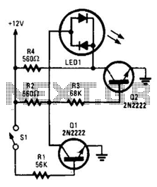
With switch SI open, base bias is supplied to transistor Q2 through a voltage divider formed by resistors R2 and R3, which activates the green element of the LED. This indicates that power is being supplied to the project....

An advantage of a photogate over a sound trigger is that the former activates based on the exact position of the object that interrupts the beam. For instance, the shape of a snapped elastic cord can be captured as...

The purpose of the receiver/interface circuit is to pass RF to the receiver through capacitor C9, while adding DC power to the feedline through resistor R2 and RF choke L7. The receiver/interface circuit is designed to facilitate the transmission of...
A project of a 555 tester circuit, the circuit will start blinking LEDs when power is applied, which will indicate that the IC is working correctly. The 555 tester circuit is designed to verify the operational status of the 555...