
FET audio mixer circuit
The FET audio mixer circuit utilizes Field Effect Transistors (FETs) to achieve high fidelity audio mixing. The use of FETs in this application is advantageous due to their high input impedance and low output impedance, which minimizes signal loss and distortion. The mixer can be configured to accept multiple audio signals, such as those from microphones or musical instruments, and combine them into a single output signal.
In this circuit, the input signals are fed into the gate terminals of the FETs. Each FET acts as a variable resistor, controlled by the voltage at the gate, allowing for precise mixing of the audio signals. The formula for R1 ensures that the input impedance remains suitable for the desired number of inputs, preventing loading effects that could degrade audio quality.
The output of the mixer can be connected to a power amplifier or directly to a recording device, depending on the application. Additionally, the design can incorporate features such as volume controls for each input channel, allowing for further customization of the audio mix.
To enhance performance, bypass capacitors may be added to filter out any unwanted noise and to stabilize the power supply. The layout of the circuit should be carefully considered to minimize interference and maintain signal integrity, particularly in environments with high electromagnetic interference.
Overall, this FET audio mixer exemplifies the effective use of FET technology in audio applications, offering flexibility and high performance for a variety of mixing needs.This FET audio mixer is an example of FET`s versatility. FETs are originally designed for high frequency applications but they can be used for audio frequencies and in fact they perform excellently in this area. The number of inputs that can be connected to the circuit is unlimited as long as the R1 value is chosen according to this formula: R1 =
22K / n, where n = the number of inputs. 🔗 External reference
Related Circuits
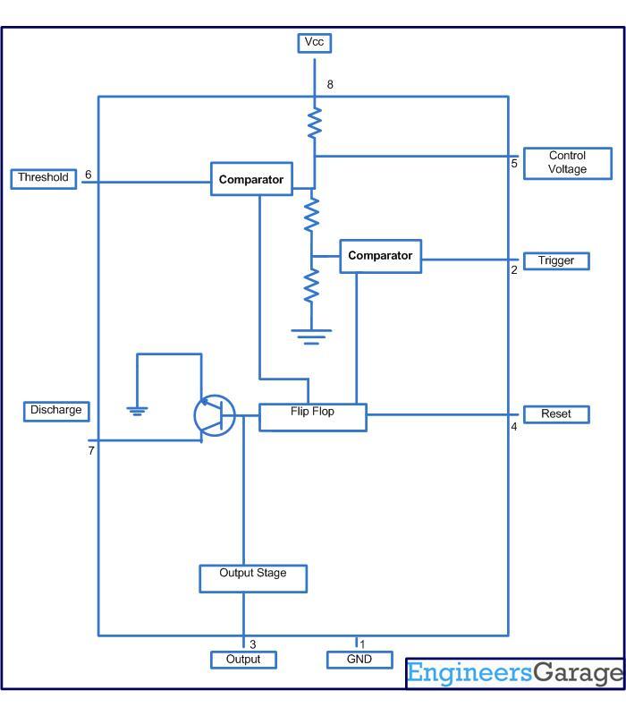
This circuit-based project demonstrates the operation of a 555 timer in astable mode to generate pulses with a time period of 0.5 seconds. These pulses can be utilized in various applications, such as blinking an LED or creating decorative...
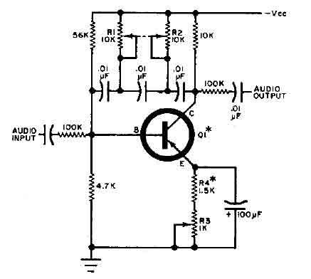
This circuit is designed for selective tuning adjustments between two closely spaced audio tones. The frequency is determined by the values of the capacitors and resistors in the feedback circuit connecting the collector and base of transistor Q1. With...
The following circuit illustrates the connection of the Devantech SRF04 Ultrasonic Sensor to the SV203 powered PPRK Circuit Diagram. This circuit is based on the Devantech SRF04 sensor and features a minimum initiation time of 10 milliseconds for the...
The amplifier operates primarily in the current domain. The first stage is a voltage controlled current sink. The second stage is a current-controlled voltage source. The fourth stage is a constant current sink. The main advantage of current domain...

A simple infrared-controlled switch can be operated using a TV remote control. The load can be any AC-powered device connected to the relay. The load activates for three minutes before turning off and can be used to switch on...
This circuit is a modification of a high and low voltage cut-off with delay and alarm circuit that was featured in Circuits Today. It has been tested and found to be reliable. The circuit can be adapted with minor...