
Q-multiplier filter circuit
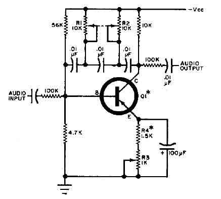
The circuit operates by utilizing a feedback mechanism that allows for fine-tuning of audio frequencies. The key component, transistor Q1, acts as an amplifier, where the feedback loop formed by the resistors and capacitors enhances the selectivity of the circuit. The capacitors determine the resonant frequency, while the resistors influence the gain and bandwidth of the response.
The three potentiometers serve a critical role in adjusting the circuit's response characteristics. By manipulating these potentiometers, the user can modify the sharpness of the response curve, which is essential for achieving the desired audio clarity and separation between the closely spaced tones. This level of control is particularly useful in applications such as audio processing, signal filtering, and tone generation.
To implement this circuit, careful selection of component values is crucial. The resistors and capacitors must be chosen to match the desired frequency response and tuning range. Additionally, proper layout and grounding techniques should be employed to minimize noise and interference, ensuring optimal performance of the circuit. The overall design should be tested and calibrated to verify that it meets the required specifications for audio applications.This circuit is selective for the tuning adjustment between two closely spaced tones audio. The frequency is dependent on the selective value capacitors and resistors in the feedback circuit between the collector and base of Q1. With the values shown, the frequency can be tuned to a hundred cycles or so-around 650 Hz Ri and R2 should be grouped.
R 3 potentiometer transmitter determines the sharpness of the response curve. Source: discovercircuits 🔗 External reference
Related Circuits
What exactly is a multivibrator? I suppose one definition would be 'a circuit which has several states'. This will do for now, it's quite loose so leaves plenty to the imagination! Conventional multivibrators have only two stages and come...
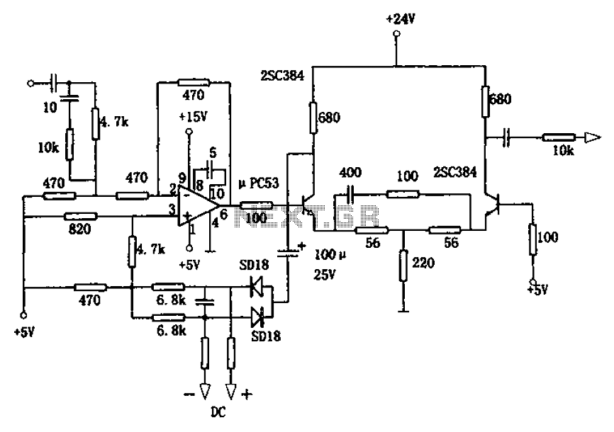
The circuit is designed for a broadband linear detection application with a bandwidth of 10 MHz. It serves as a millivoltmeter measuring instrument suitable for frequencies exceeding 10 MHz. The circuit features a linear detector utilizing operational amplifiers, specifically...
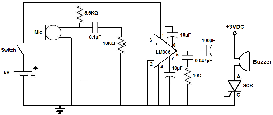
This circuit is designed to activate an alarm when it detects sound above a specified threshold. The alarm serves as a notification for any sound in areas that are typically quiet, such as quiet zones. Under normal quiet conditions,...
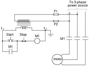
The most challenging aspect of interpreting ladder diagrams, particularly for individuals familiar with electronic schematic diagrams, is the representation of electromechanical relays. The operation of a motor control circuit should be explained, detailing what occurs when the "Run" switch...
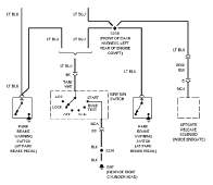
The following circuit illustrates the wiring diagram and electrical circuit troubleshooting for the 1997 Chevrolet Blazer. Features include a 4.3-liter Vortec V-6 engine, an AM-FM stereo radio with CD player, rear-wheel drive managed by a four-speed automatic transmission, air...
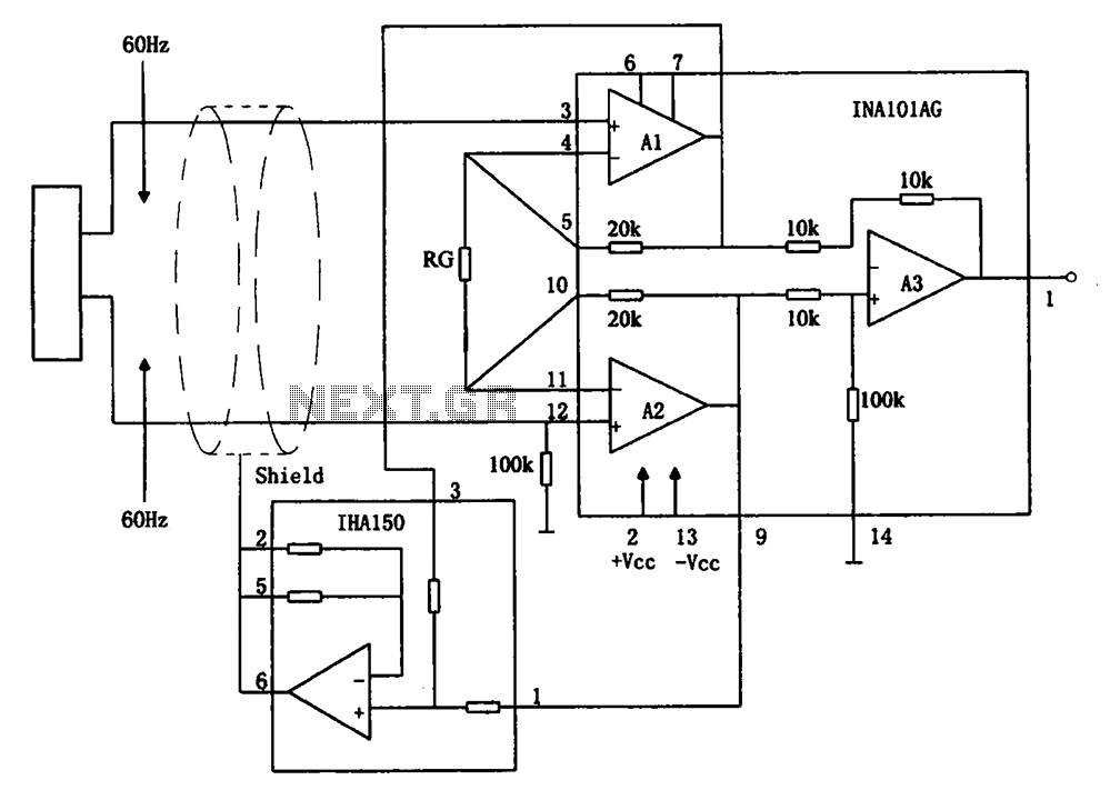
The circuit diagram illustrates a hum elimination instrument amplifier circuit. The amplifier stages A1 and A2 utilize the integrated operational amplifier INA101, followed by stage A3 which employs the INA105. A feedback circuit is incorporated to reduce the power...
Warning: include(partials/cookie-banner.php): Failed to open stream: Permission denied in /var/www/html/nextgr/view-circuit.php on line 713
Warning: include(): Failed opening 'partials/cookie-banner.php' for inclusion (include_path='.:/usr/share/php') in /var/www/html/nextgr/view-circuit.php on line 713