FET Audio Mixers
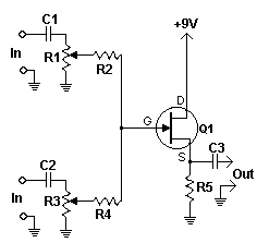
A compact and straightforward audio mixer utilizing a limited number of components centered around a FET transistor (2N3819).
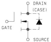
This audio mixer circuit is designed to combine multiple audio signals into a single output while maintaining signal integrity and minimizing distortion. The core component, the 2N3819 FET transistor, serves as a voltage-controlled resistor, allowing for effective mixing of audio signals.
The circuit typically includes several input channels, each equipped with a potentiometer to adjust the volume of the respective audio source. These potentiometers are connected to the gate of the FET, which modulates the signal levels based on the resistance set by the potentiometers. This configuration allows for smooth transitions and adjustments in audio levels, making it suitable for live sound applications or small recording setups.
The output stage of the mixer is connected to a coupling capacitor, which blocks any DC offset while allowing the AC audio signals to pass through. This ensures that the output signal is clean and suitable for further amplification or processing.
Power supply considerations for this circuit are crucial; typically, a dual power supply (positive and negative voltages) is used to ensure that the FET operates within its optimal range. Bypass capacitors should be included near the power pins to filter out any noise and stabilize the power supply.
Overall, this small audio mixer circuit is an effective solution for basic audio mixing tasks, leveraging the properties of the 2N3819 FET to achieve a simple yet functional design. It is ideal for hobbyists and professionals looking for a cost-effective and space-efficient mixing solution.Small simple audio mixer with a few components around one FET transistor (2N3819).. 🔗 External reference
