
Audio Power Meter
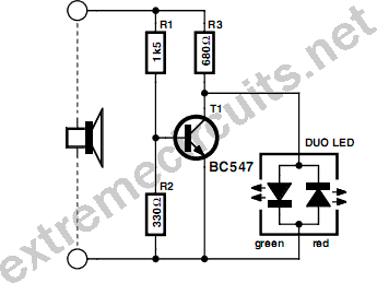
This circuit serves as a visual power indicator for loudspeakers, effectively utilizing a dual-color LED to represent varying power levels. The design incorporates a simple yet effective voltage divider and transistor configuration to achieve the desired functionality. The dual-color LED operates based on the output signal from the amplifier, providing real-time feedback on the power being delivered to the loudspeaker.
The circuit is structured with R1 and R3 forming a parallel combination, resulting in a total resistance of 470 Ohms. This value is critical as it ensures that the additional load does not adversely affect the amplifier's performance. The LED's color indication is a direct consequence of the voltage levels present during different cycles of the audio signal.
During the positive half cycle, if the voltage surpasses the activation threshold, the green LED lights up. As the output voltage increases, T1 is triggered to conduct, leading to the green LED turning off and the transition to orange as the red LED begins to illuminate during the negative half cycle. The transition region is particularly interesting as it provides a smooth shift in color, indicating that the power is approaching a critical level.
The choice of resistor values plays a vital role in calibrating the circuit for specific applications. The provided values are designed for typical home audio setups, allowing users to gauge their amplifier's output effectively. The circuit's robustness is enhanced by the use of standard 0.25 W resistors, ensuring reliability within the specified power limits.
It is essential to note that the power levels indicated by this circuit are tailored for 4-Ohm speakers. Users employing 8-Ohm speakers must adjust the resistor values accordingly to maintain accuracy in power indication. This circuit exemplifies a straightforward yet effective approach to monitoring audio power levels, providing users with an intuitive visual representation of their amplifier's output.This simple circuit indicates the amount of power that goes to a loudspeaker. The dual-color LED shows green at an applied power level of about 1 watt. At 1. 5 watts it glows orange and above 3 watts it is bright red. The circuit is connected in parallel with the loudspeaker connections and is powered from the audio signal. The additional load that this represents is 470 Ohm (R1//R3) will not be a problem for any amplifier. During the positive half cycle of the output signal the green LED in the dual-color LED will be turned on, provided the voltage is sufficiently high. At higher output voltages, T1 (depending on the voltage divider R2/R1) will begin to conduct and the green LED will go out.
During the negative half cycle the red LED is driven via R3 and will turn on when the voltage is high enough. In the transition region (where T1 conducts more and more and throttles` the green LED as a result) the combination of red/green gives the orange colour of the dual-LED.
By choosing appropriate values for the resistors the power levels can be adjusted to suit. The values selected here are for typical living room use. You will be surprised at how loud you have to turn your amplifier up before you get the LEDs to go! The resistors can be 0. 25 W types, provided the amplifier does not deliver more than 40 W continuously. Above this power the transistor will not be that happy either, so watch out for that too. Because T1 is used in saturation, the gain (Hfe) is not at all important and any similar type can be used. The power levels mentioned are valid for 4-Ohm speakers. For 8-Ohm speakers all the resistor values have to be divided by two. 🔗 External reference
Related Circuits
Can be directly connected to CD players, tuners and tape recorders. The circuit described above can be interfaced directly with various audio devices such as CD players, tuners, and tape recorders. This indicates that the circuit is designed to handle...
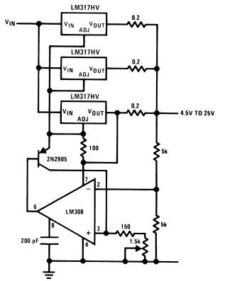
The LM317HV adjustable regulator is capable of supplying more than 1.5A across an output voltage range of 1.2V to 57V. The design of this high-current power supply is straightforward, as the LM317HV requires only a few external resistors to...
Opamps are very useful. But one of their major drawbacks is the requirement of a dual supply. This seriously limits their applications in fields where a dual supply is not affordable or not practicable. This circuit solves the problem...
Soft power for a large transformer is implemented by using a series resistance of 100 ohms at 10 watts, or alternatively, two resistors of 47 ohms at 5 watts each in the primary circuit. The resistance is bypassed by...
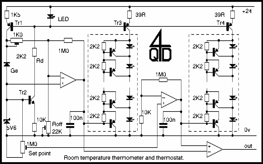
This circuit uses a germanium diode (marked Ge) as a temperature sensor. I used an OA90 diode but others should do. The 'ring' of Tr1 and Tr2 bias each other. Tr1's collector current is stabilized by the 5v6 zener,...
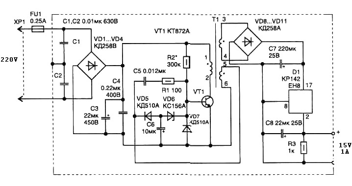
A 15 Watt switching power supply schematic diagram features a pulse transformer T1 constructed on a ferrite core M2500NMS-2 or M2000NM9, with a Sh5h5 size (cross-section of the magnetic coils at the location of 5G—5 mm with a gap...
Warning: include(partials/cookie-banner.php): Failed to open stream: Permission denied in /var/www/html/nextgr/view-circuit.php on line 713
Warning: include(): Failed opening 'partials/cookie-banner.php' for inclusion (include_path='.:/usr/share/php') in /var/www/html/nextgr/view-circuit.php on line 713