
FET VOLTMETER
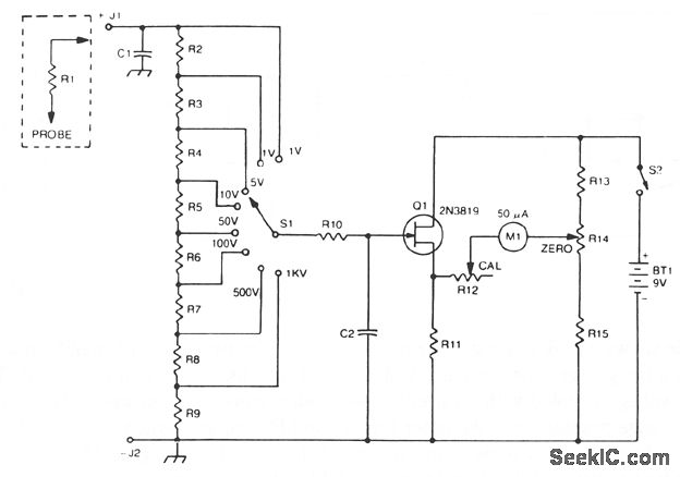
The circuit utilizes the 2N3819 field-effect transistor (FET) in a cathode follower configuration, which is advantageous for its high input impedance and low output impedance characteristics. This makes it suitable for buffering signals without significant loading effects on the preceding stage. The FET operates in the linear region, allowing for accurate voltage tracking.
The bias offset is crucial for ensuring that the meter reads correctly at zero input. Resistors R14 and R12 are strategically chosen to set the quiescent point of the FET, allowing for precise adjustments to achieve the desired meter null. The values of R2 through R9 are selected to provide a combined resistance of approximately 10 MΩ, which is necessary for the full-scale calibration of the VOM. This ensures that the meter can accurately measure a wide range of voltages.
Resistor R10 serves a protective role in the circuit, safeguarding the FET from excessive current that could lead to damage. This is particularly important in applications where the input voltage may vary significantly. Additionally, capacitor C2 is included to provide AC bypassing, which effectively filters out high-frequency noise and RF interference that could affect the accuracy of the measurements. By ensuring a clean signal is presented to the FET, the overall performance and reliability of the voltage output meter are enhanced.
In summary, the 2N3819 FET-based VOM circuit is designed for high accuracy and stability in voltage measurements, incorporating essential components for calibration, protection, and noise reduction.A2N3819 FET provides a solid state VOM ‚The 2N3819 acts as a cathodefollowerin a VOM The biasoffset(meter null) is obtained with R14 and R12 sets full scale calibration R2 through R9 should totalabout10 M © R10 is a protective resistor and C2 provides ac bypassing to limit rf and noise pickup 🔗 External reference
Related Circuits
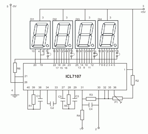
The copyright of this circuit is owned by Smart Kit Electronics. This document discusses improvements and modifications based on the original schematic. It describes a straightforward yet highly accurate and useful digital voltmeter designed as a panel meter, suitable...
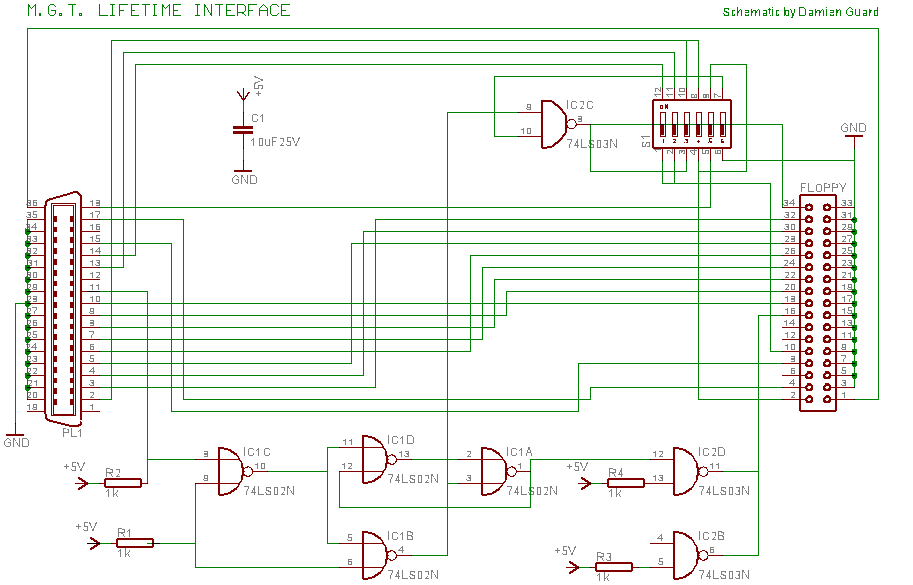
The Lifetime Drive, later renamed the Universal Drive due to concerns regarding implied warranties, was manufactured by Miles Gordon Technology (MGT) in April 1989. This floppy drive was designed to connect to most popular computers of that era. MGT...
The text discusses experiences with common base or grounded base designs and bipolar transistors in regenerative stages, noting that bipolar transistors can provide higher amplification than FETs. It also mentions challenges faced with a radio project that included a...
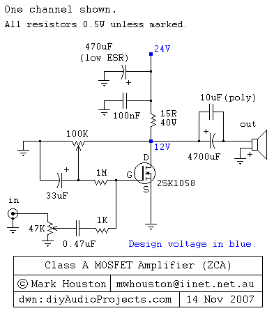
This weblog discusses electronic circuit schematics, PCB design, DIY kits, and electronic project diagrams. It features a simple Class A MOSFET amplifier using the 2SK1058 component. The circuit operates with a 24V supply voltage at high current. It incorporates...
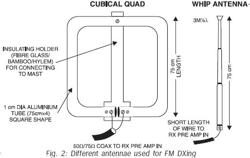
FM transmissions can be received within a range of 40 km. In fringe areas, the signal may be very weak. FM DXing refers to the practice of receiving distant stations (1500 km or more) on the FM band (88-108...
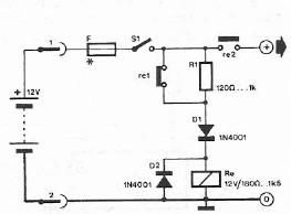
Safety polarity connection circuit design using common electronic components The safety polarity connection circuit is designed to ensure that electronic devices are connected with the correct polarity, preventing damage from reversed connections. This circuit typically employs common electronic components such...
Warning: include(partials/cookie-banner.php): Failed to open stream: Permission denied in /var/www/html/nextgr/view-circuit.php on line 713
Warning: include(): Failed opening 'partials/cookie-banner.php' for inclusion (include_path='.:/usr/share/php') in /var/www/html/nextgr/view-circuit.php on line 713