
MOSFET-BASED PREAMPLIFIER FOR FM RADIO Project PCB
The circuit design utilizes the dual-gate MOSFET BF966S to achieve an effective FM preamplifier configuration. The dual-gate structure allows for enhanced control over gain and dynamic range, making it suitable for both amateur radio applications and more extensive broadcasting needs. The preamplifier circuit is designed to accept input from various antenna types, ensuring versatility in reception capabilities, particularly in areas with weak signals. The use of trimmers and preset resistors allows for fine-tuning of gain, ensuring optimal performance under varying conditions. The careful selection of capacitors for input and output stages enhances impedance matching, contributing to improved signal integrity and overall performance. The PCB layout considerations, including the placement of the MOSFET and the use of an epoxy substrate, aim to minimize parasitic effects, further enhancing the circuit's reliability and efficiency. The integration of a suitable power supply and the option for outdoor installation underscore the circuit's adaptability for diverse operational environments.FM transmissions can be received within a range of 40 km. If you are in fringe areas, you may get a very weak signal. FM DXing refers to hearing distant stations (1500 km or more) on the FM band (88-108 MHz). The term DX` is borrowed from amateur radio operators. It means distance unknown`; D` stands for distance` and X` stands for unknown. ` For a n FM receiver lacking gain, or having a poor signal-to-noise ratio, using an external preamplifier improves the signal level. The dual-gate MOSFET preamplifier circuit shown in Fig. 1 gives an excellent gain of about 18 dB. It costs less and is simple to design. Field-effect transistors (FETs) are superior to bipolar transistors in many applications as these have a much higher gain ”approaching that of a vacuum tube.
These are classified into junction FETs and MOSFETs. On comparing the FETs with a vacuum tube, the gate implies the grid, the source implies the cathode, and the drain implies the plate. In a transistor, the base implies the grid, the emitter implies the source, and the collector implies the drain.
In dual-gate FETs, gate 1 is the signal gate and gate 2 is the control gate. The gates are effectively in series, making it easy to control the dynamic range of the device by varying the bias on gate 2. The MOSFET is more flexible because it can be controlled by a positive or negative voltage at gate 2.
The resistance between the gate and rest of the device is extremely high because these are separated by a thin dielectric layer. Thus the MOSFET has an extremely high input impedance. Dual-gate MOSFETs (DG MOSFETs) are very popular among radio amateurs. These are being used in IF amplifiers, mixers, and preamplifiers in HF-VHF transceivers. The isolation between the gates (G1 and G2) is relatively high in mixer applications. This reduces oscillator pulling and radiation. The oscillator pulling is troublesome particularly in shortwave communications. It is a characteristic in many unsophisticated frequency-changer stages, where the incoming signal, if large, pulls the oscillator frequency slightly off the frequency set by the tuning knob and towards a frequency favourable to the (large) incoming signal.
A DG MOSFET can also be used for automatic gain control in RF amplifiers. DG MOSFET BF966S is an n-channel depletion-type MOSFET that is used for general-purpose FM and VHF applications. In this configuration, it is used for FM radio band. The quadratic input characteristic of the FET input stage gives better results than the exponential characteristic of a bipolar transistor.
Gate 1 is meant for input and gate 2 is for gain control. The input from the antenna is fed to gate G1 via C1 and L1. Trimmer VC1 is used to tune and select the input frequencies. Capacitor C4 (100 kpF) at the gain control electrode (gate 2) decouples any variation in G2 voltage at radio frequencies to maintain constant gain. Set preset VR (47k) to adjust the gain or connect a fixed resistor for fixed gain. The output of the circuit is obtained via capacitor C5 and fed to the FM receiver amplifier. For indoor use, connect a - wavelength whip antenna, ½-wavelength 1. 5m wire antenna, or any other indoor antenna set-up with this circuit. You may use a 9V battery without the transformer and diode 1N4007, or any 6V-12V power supply to power the circuit (refer Fig.
1). The RF output can be taken directly through capacitor C5. For an improved input and output impedance, change C1 from 1 kpF to 22 pF and C5 from 1 kpF to 100 kpF. For outdoor use at top mast, like a TV booster, connect the C5 output to the power supply unit (PSU) line.
Use RG58U/ RG11 or RG174 cable for feeding the power supply to the receiver amplifier. The PSU for the circuit is the same as that of a TV booster. For TV boosters, two types of mountings are employed: The fixed tuned booster is mounted on the mast of the antenna. The tunable booster consisting of the PSU is placed near the TV set for gain control of various TV channels.
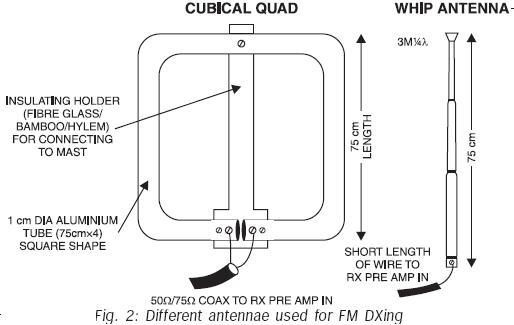
(For details, refer High-Gain 4-Stage TV Booster` on page 72 of Electronics Projects Vol. 8. ) Mount the DG MOSFET BF966S at the solder side of the PCB to keep parasitic capacitance as small as possible. Use an epoxy PCB. After soldering, clean the PCB with isopropyl alcohol. Use a suitable enclosure for the circuit. All component leads must be small. Avoid shambled wiring to prevent poor gain or self oscillations. Connecting a single-element cubical quad antenna to the circuit results in Open Sesam` for DXing. You can use a folded dipole or any other antenna. However, an excellent performance is obtained with a cubical quad antenna (refer Fig. 2) and Sangean ATS- 803 world-band receiver. In an amplifier, FET is immune to strong signal overloading. It produces less cross-modulation than a conventional transistor having negative temperature coefficient, doesn`t succumb to thermal runaway at high frequencies, and decreases noise.
In VHF and UHF, the MOSFET produces less noise and is comparable with JFETs. DG FETs reduce the feedback capacitance as well as the noise power coupled to the gate from the channel, giving stable unneutralised power gain for wide-band applications. This circuit can be used for other frequency bands by changing the input 🔗 External reference
Related Circuits
This is highly illegal. As a consumer, compliance with Part 15 of the rules and regulations is mandatory. Part 15 stipulates that a device must accept any interference it receives and must not cause harmful interference, such as jamming...
This circuit utilizes a 555 timer configured to operate in astable mode. This setup generates a continuous output through Pin 3 in the form of a square wave. When the timer's output transitions to a high state, it triggers...
This project provides the schematic and the parts list needed to construct a 3V FM transmitter. This FM transmitter is one of the simplest and most basic transmitters to build, yet it offers a useful transmitting range. It is...
A 4-position slide switch is utilized to activate different colored LEDs based on its position. Additionally, it is required to adjust the output frequency of a 555 timer operating in astable mode to drive a piezo buzzer. The challenge...
This circuit was inspired by a friend who wanted a reverb for his portable guitar amplifier. I originally tried using NE5532 low noise op-amps for the buffer stages but they were too noisy for the low level circuits so...
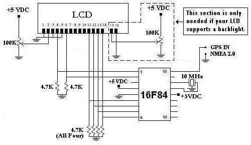
This is a project that I started back late 2003 when I just starting to learn PIC programming. I wanted to building something that actually did something useful. This project is based on a PIC16F84. I actually came up...