
Field Strength Meter II
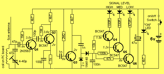
The described project encompasses a multifaceted electronic device that serves as a Field Strength Meter, a Frequency Meter, and a tool for testing detuned transmitters. Each feature of this device is crucial for applications in radio frequency (RF) engineering, particularly in the design and evaluation of transmitters.
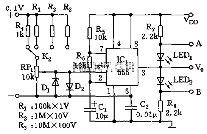
The core functionality of the Field Strength Meter is to measure the strength of RF signals. This is vital for assessing the performance of transmitters, as it provides quantitative data regarding signal strength, which can be used to determine transmitter efficiency and expected operational range. The device operates by receiving RF energy through a 5 cm antenna, which is designed to capture a range of frequencies effectively.
The circuit architecture begins with a tuned front end that selectively filters the incoming RF signals. This section ensures that only the desired frequency range is processed, minimizing interference from unwanted signals. Following the front end, the RF signal is amplified using an RF amplifier, which boosts the signal strength for further processing.
The design includes two additional stages of amplification to ensure that the output signal is sufficiently strong for accurate measurement. These stages are critical in enhancing the signal-to-noise ratio, allowing for precise readings even in environments with significant background RF noise.
A diode pump is incorporated into the circuit to rectify the amplified RF signal, converting it into a form that can be easily measured. This component plays a key role in translating the RF energy into a usable voltage that corresponds to the field strength being measured.
Lastly, a transistor staircase is utilized to provide a visual representation of the measured signal strength. This component allows for easy interpretation of the readings, enabling users to observe variations in signal strength in real-time.
Overall, this project demonstrates a sophisticated approach to RF measurement, integrating multiple functionalities into a single device that is essential for engineers and technicians working with RF systems.This project has 3 features. 1. It`s a Field Strength Meter, 2. A Frequency Meter and, 3. An aid for testing detuned transmitters. Its uses will become clear in a moment but firstly let`s go over the background of a Field Strength Meter. A Field Strength Meter is essential when designing and building transmitters. It provides signal strength values and allows us to compare and estimate the efficiency of a transmitter and its expected range.
The circuit consists of a tuned front end, an RF amplifier, two further stages of amplification, a diode pump and a transistor staircase. The circuit picks up RF energy on its 5cm antenna and passes it to a tuned circuit where all the frequencies, EXCEPT
🔗 External reference
Related Circuits
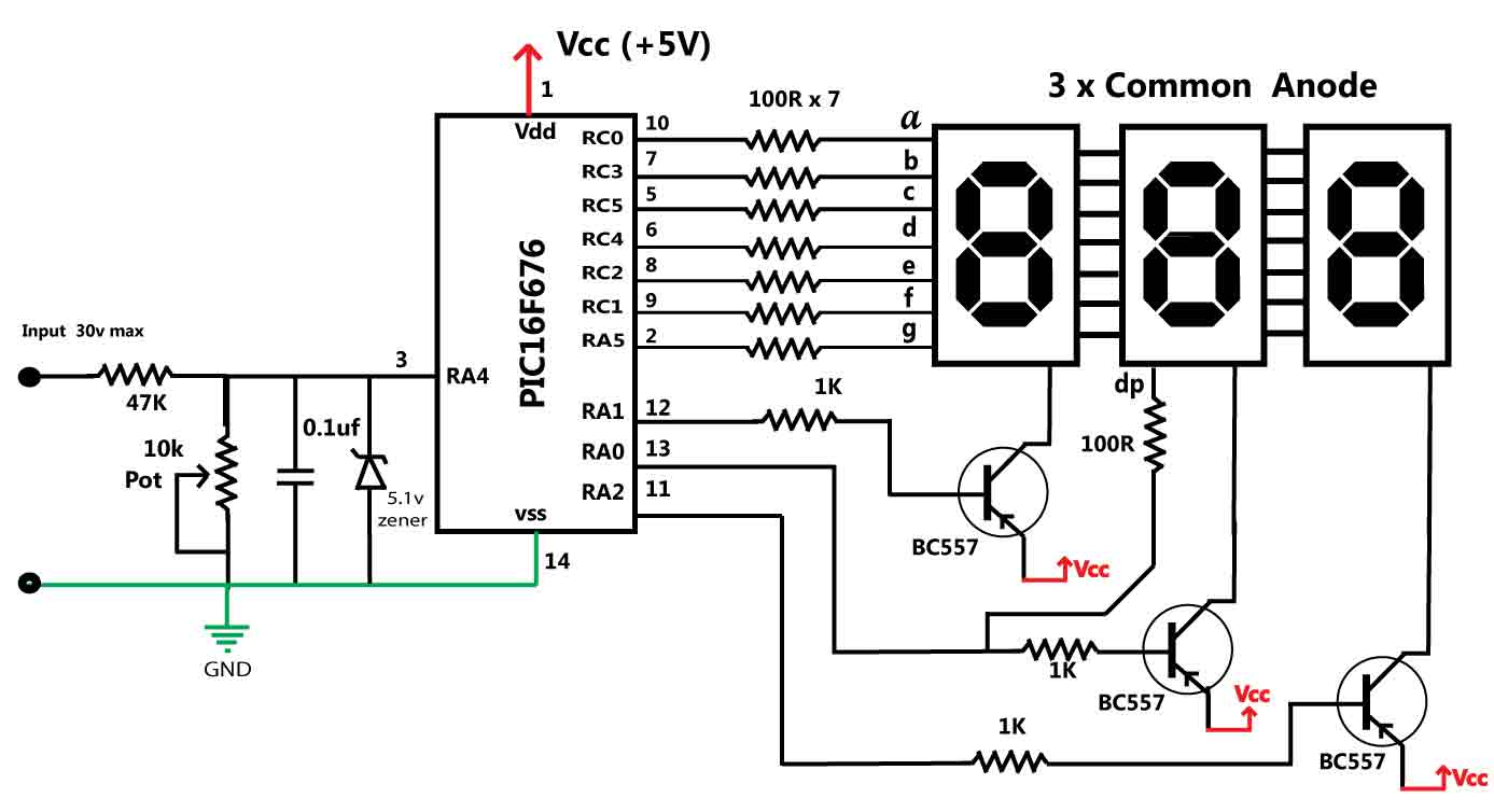
This is a simple application of the internal 10-bit ADC (analog-to-digital converter) of the PIC16F676 microcontroller. This circuit can be used to measure up to 30 V DC. Possible applications include a benchtop power supply or as a panel...
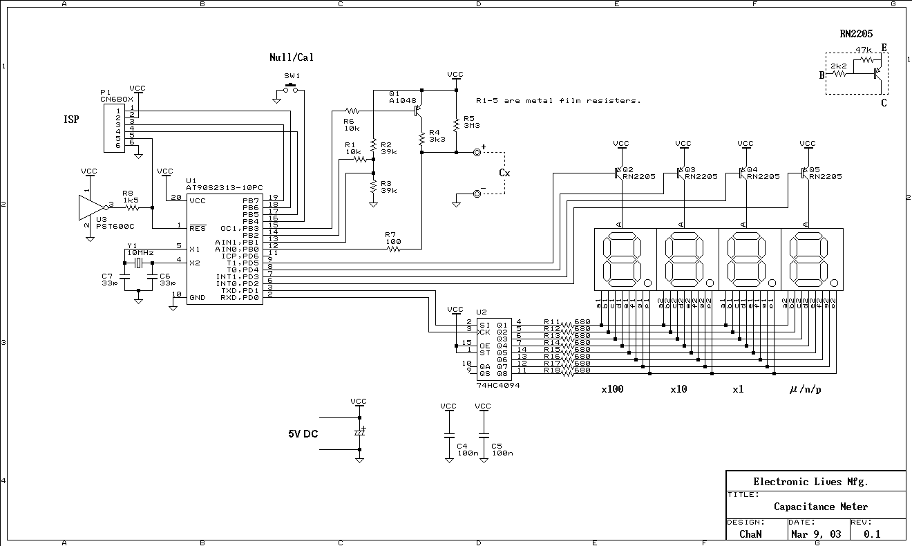
This is a simple capacitance meter which can measure capacitance value easy. There are some measurement methods for capacitance, at one time the capacitance was measured with a impedance bridge or a dip meter. Recently typical capacitance meters can...
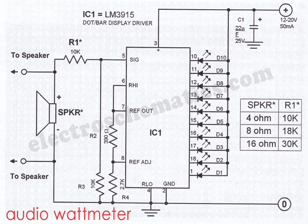
This sound wattmeter utilizes a series of colored LEDs as a scale to display the relative power output of an amplifier in watts. It is designed for easy integration into a speaker box, requiring only a connection to a...
The control terminal at 5 feet and the threshold end at 6 feet represent two internal input voltage comparators. As long as the voltage at 6 feet exceeds the voltage at 5 feet by 5 mV, the 555 timer...
The TPA2011D1 is a 3.2-W high-efficiency, filter-free Class-D audio power amplifier housed in a 1.21 mm x 1.16 mm wafer chip scale package (WCSP) that requires only three external components. This amplifier features 95% efficiency, an 86-dB power supply...

An expanded scale voltmeter (ESV) can be crucial for aircraft operation. This assertion is based on the dependency of the radio link, which allows control of the aircraft, on nickel-cadmium (NiCd) batteries located in both the transmitter and receiver....
Warning: include(partials/cookie-banner.php): Failed to open stream: Permission denied in /var/www/html/nextgr/view-circuit.php on line 713
Warning: include(): Failed opening 'partials/cookie-banner.php' for inclusion (include_path='.:/usr/share/php') in /var/www/html/nextgr/view-circuit.php on line 713