
Audio Wattmeter Circuit with LM3915
The sound wattmeter circuit is built around the LM3915 LED bar graph/LED dot display driver, which is capable of driving up to 10 LEDs in a linear fashion. The circuit can be powered by a DC adapter providing between 12 to 20 volts, ensuring that the LED display is adequately illuminated for clear visibility. The use of colored LEDs allows for a straightforward interpretation of power levels, with different colors representing different ranges of output power.
The resistance value R1 is critical as it determines the sensitivity of the wattmeter based on the speaker impedance. The accompanying table provides specific resistance values tailored for common speaker impedances, such as 4 ohms and 8 ohms. This ensures accurate readings of power output relative to the connected speaker.
The circuit’s design accommodates the positive swing of the audio signal, which is sufficient for most amplifier testing purposes. The sine wave input, commonly used in audio testing, allows for a consistent representation of power output. Additionally, for scenarios where an actual speaker is not available, the option to connect a dummy load resistor provides flexibility in testing the wattmeter’s functionality without compromising accuracy.
In summary, this sound wattmeter circuit is a practical tool for audio engineers and enthusiasts, offering a simple yet effective means of measuring amplifier power output through a visual LED display. Its ease of integration and adaptability to different speaker impedances make it a valuable addition to any audio testing setup.This sound wattmeter uses a row of colored LEDs as a scale to show the relative power output of your amplifier in watts. It is easy to be inserted into the speaker box. All you need is to hook a supply voltage to it. The value of R1 depends upon the impedance of the speaker being used. The table near the sound wattmeter diagram shows the necessary values of R1. The supply voltage of the circuit is 12 20 volts/50 mA DC adapter. Take note that the LM3915 indicates only the positive swing of the signal. Anyway, by testing amplifiers it does not matter anyhow since a sine wave is normally used as a test signal. To test the circuit without using an actual speaker, you can connect a dummy resistor with a value of either 8 or 4 ohms.
🔗 External reference
Related Circuits
The regenerative effect of a 4-quadrant inverter necessitates power dissipation in some form. In large industrial drives, this power is typically re-inverted back onto the national grid. However, for smaller applications, implementing a braking circuit is advisable. For low-power...
One of the most notable RF amplifiers documented is Wes Hayward's post-mixer amplifier in the Progressive Communications Receiver. It is recognized as a highly effective high-level RF amplifier, operating with a standing current of 50 mA, which allows it...
The circuit was originally available in kit form from a surplus supplier, but it is likely more widely accessible now. It introduces innovative concepts such as utilizing a 555 timer as a pulse width modulator (PWM) and employing serial/parallel...
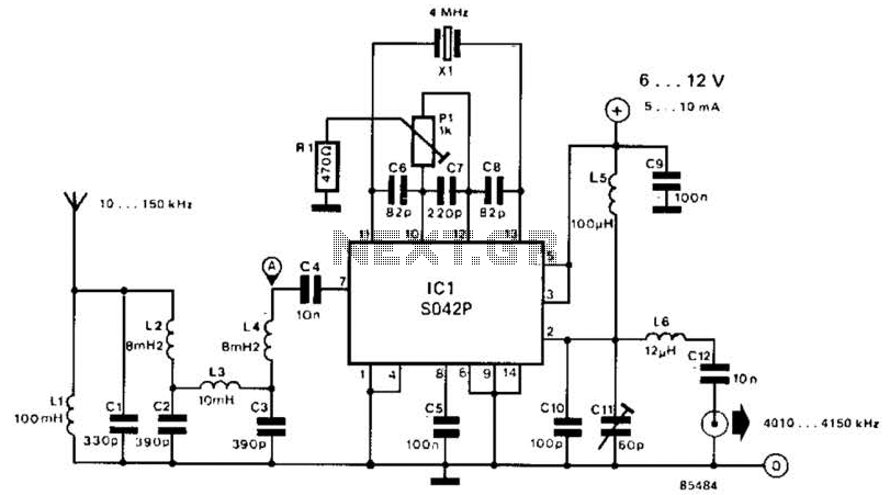
This converter shifts frequencies from 10 kHz to 150 kHz up to 4.01 to 4.15 MHz, suitable for use with a shortwave receiver for very low frequency (VLF) reception. A 4 MHz local oscillator frequency is utilized, and the...
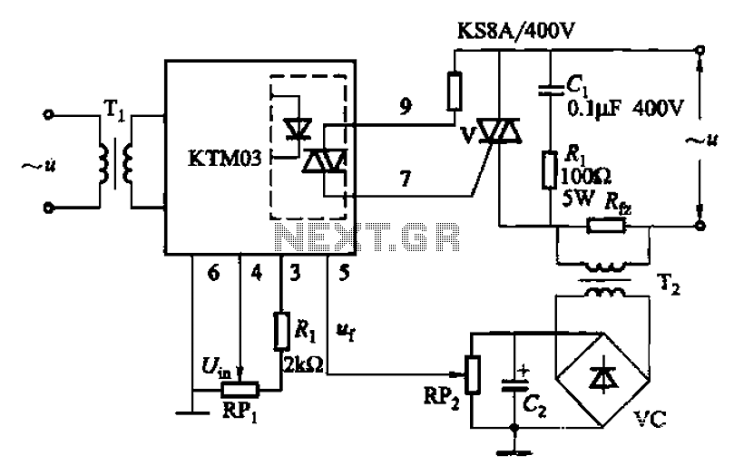
An adjustment potentiometer (RP) is utilized to set the voltage across the load resistor (Rfz) to a predetermined value. The real-time closed-loop control is achieved through the potentiometer (RPz). Open-loop control is functional as long as the feedback voltage...
A small circuit designed for various time measurement applications. It features an audible sound signal from the buzzer BZ1 and has the capability to drive an external circuit through the optocoupler IC2, once the appropriate circuit is connected to...