
filter Strange behavior from variable-gain amplifier
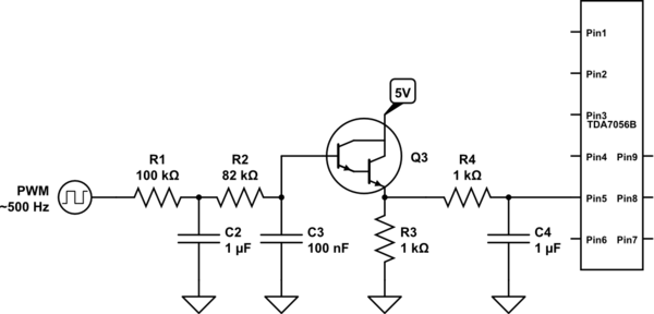
In this circuit, pin 5's voltage serves as a control input for gain adjustment, where the specified range of 0.4 to 1.2 V was initially established using traditional components. The transition to an Arduino-based approach introduces a digital control mechanism, leveraging the microcontroller's capabilities to generate a Pulse Width Modulation (PWM) signal. The PWM signal is subsequently filtered to provide a smoother analog voltage output suitable for gain control.
The use of a Darlington pair as a voltage follower is significant due to its high input impedance and ability to provide substantial current gain. This configuration ensures that the output voltage closely follows the filtered PWM input, allowing for precise control of the gain based on the varying input voltage. It is essential to note that the change in the required voltage range for gain control—from 0.4-1.2 V to 1.22-2.25 V—could be attributed to several factors, including the characteristics of the Darlington pair, variations in the filtering process, or differences in the internal resistance and thresholds of the components used in the Arduino setup compared to the original circuit.
Understanding these discrepancies is crucial for optimizing the circuit's performance and ensuring consistent behavior across different configurations. Further investigation into the filtering method and the characteristics of the Darlington pair may provide insights into achieving the desired gain control with the original voltage specifications.It takes a voltage between 0. 4 and 1. 2 V on pin 5 to control its gain. In the first two versions of the circuit, I used logic ICs and/or counters and an op amp with a resistor network for a DAC to provide the voltage, and all worked well. This last week, I decided to try my hand at doing the same with an Arduino doing the logic work, and instead of an op amp DAC, I`m filtering a PWM
signal and feeding it to a darlington-pair voltage follower. It took a while to get it right, but now it works. The odd part is, the voltage range that produces the correct gain variation is completely different: 1. 22 V to 2. 25 V. I`m happy that it works, but I`m very curious as to why that is. 🔗 External reference
Related Circuits
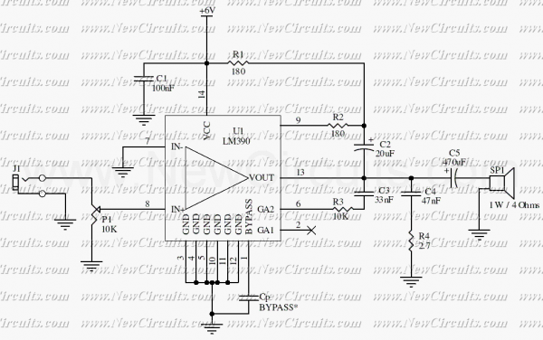
This circuit is a mono audio amplifier that will boost low frequencies as you see at the frequency response. The circuit is suitable for driving a subwoofer speaker for example. The output power of the circuit is about 1...
The capacitor filter operates by measuring the capacitance, which is proportional to the pulse width. This measurement is compared to a nominal capacitance to determine qualification. The circuit, as illustrated in the accompanying figure, includes IC1 along with resistors...
The LM2876 audio power amplifier circuit can be designed as a simple, high-efficiency power audio amplifier capable of delivering 40W of continuous average power to an 8-ohm load with a total harmonic distortion plus noise (THD+N) of 0.1% from...

Application of the differential amplifier circuit in OTL amplifier circuits. The differential amplifier circuit is a fundamental building block in various electronic applications, particularly in output transformerless (OTL) amplifier circuits. An OTL amplifier is designed to drive loads directly...
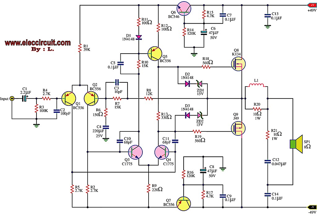
This is the first MOSFET power amplifier designed, featuring a comprehensive circuit. As a 60-watt power amplifier, it is adequate for typical usage. The 60-watt MOSFET power amplifier circuit is designed to deliver high efficiency and robust performance for audio...
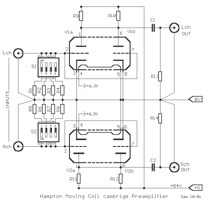
A very good circuit of pre-preamplifier for amplification of signals from heads of Moving Coil. It uses the two departments of tube ECC88, association parallel, for reduction of produced noise. The circuit enters in line with existing circuit PHONO....
Warning: include(partials/cookie-banner.php): Failed to open stream: Permission denied in /var/www/html/nextgr/view-circuit.php on line 713
Warning: include(): Failed opening 'partials/cookie-banner.php' for inclusion (include_path='.:/usr/share/php') in /var/www/html/nextgr/view-circuit.php on line 713