
555 capacitor filter circuit diagrams
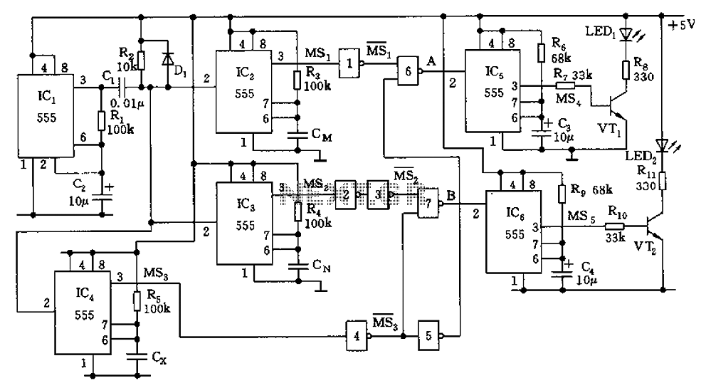
The described circuit utilizes an astable multivibrator configuration to generate a square wave that serves as a timing reference for the subsequent monostable circuits. The astable multivibrator, composed of IC1, R1, and C2, continuously oscillates, resulting in a periodic output that is essential for triggering the monostable circuits (IC2, IC3, IC4). These monostable circuits respond to the square wave output by generating a single output pulse whose width is contingent upon the charging and discharging characteristics of their respective capacitors.
The measured capacitance (Cx) is compared against predefined limits (Cm and Cn). The circuit effectively determines if the measured capacitance falls within acceptable bounds. If Cx exceeds Cm, LED1 activates, signaling that the capacitance is above the minimum threshold. Conversely, if Cx is lower than Cn, LED2 activates, indicating that the capacitance exceeds the maximum threshold. The NAND gates serve as a logical check to ensure that the output conditions are met before allowing the 555 timer to set, thus controlling the overall operation and indicating the status of the capacitor being tested.
In conclusion, this circuit provides a robust solution for capacitance measurement and qualification, utilizing standard IC components to achieve the desired functionality. The use of visual indicators (LEDs) enables easy interpretation of the test results, while the design ensures reliability and precision in capacitance evaluation. Capacitor filter works by the capacitance being measured is proportional to the pulse width and pulse width qualifying nominal capacitance comparing screening to detect. Circui t shown in Figure, IC1 and R1, C2 composition astable multivibrator, a period of about 1.4 seconds to produce a square wave pulse. In IC2, IC3, IC4 as the core component monostable trigger circuit, the timing of the trigger pulse width depending on their charge and discharge time constants.
Cx is measured capacitance, Cm, Cn is qualified capacitor capacitance of the upper and lower limit. That Cm Cx Cn. IC2, IC3, IC4 by IC1 output with square wave trigger, resulting in their different width, comparing the door circuit. Then trigger IC5, IC6 monostable circuit, the NAND gate 6,7 if not negative output pulses, 555 will not be set, 3 feet was low, VT1, VT2 off, LED1, LED2 are not light indicating that the capacitor under test qualified.
If LED1 luminous flash indicating Cx is greater than Cm; if LED2 luminous flash indicating that less than Cx Cn, capacity overrun. IC5, IC6 one-shot pulse generating about 0.8 seconds.
Related Circuits

The 78W series voltage regulators are designed to handle an input voltage of approximately 35V, while the 24V type can withstand up to 40V. It should be noted that these regulators will not operate effectively with a significant input-output...

It is a self-oscillating voltage booster. It is relatively simple to build and it will allow you to use almost all the power in the battery, even when its voltage is low. The self-oscillating voltage booster is a circuit designed...
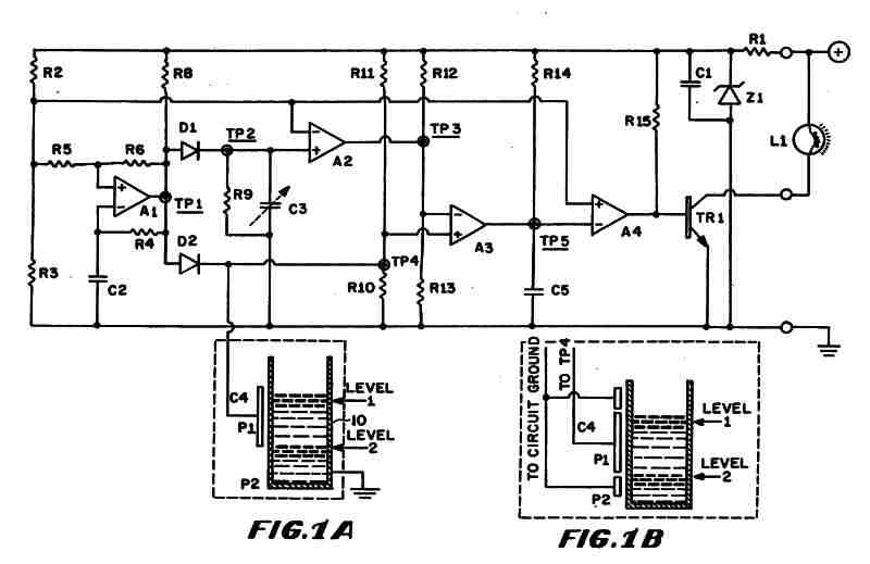
Figure 1 (A) depicts the circuit diagram of one embodiment of the fluid level detector designed. The circuit is typically powered by a 12-volt automobile battery, which is reduced to a 5-volt DC source using a voltage regulator consisting...
The latest addition to the collection of Infrared (IR) Repeater circuits, the Mark 5, is an enhanced version of the Mark 1 circuit and features an increased range. The Mark 5 Infrared Repeater circuit is designed to extend the range...
The circuit operates in a parallel-fed configuration, as the DC plate current does not pass through the inductor. R3 can be substituted with an RF choke if desired. Capacitor C3 prevents B+ from appearing across the variable capacitor, which...
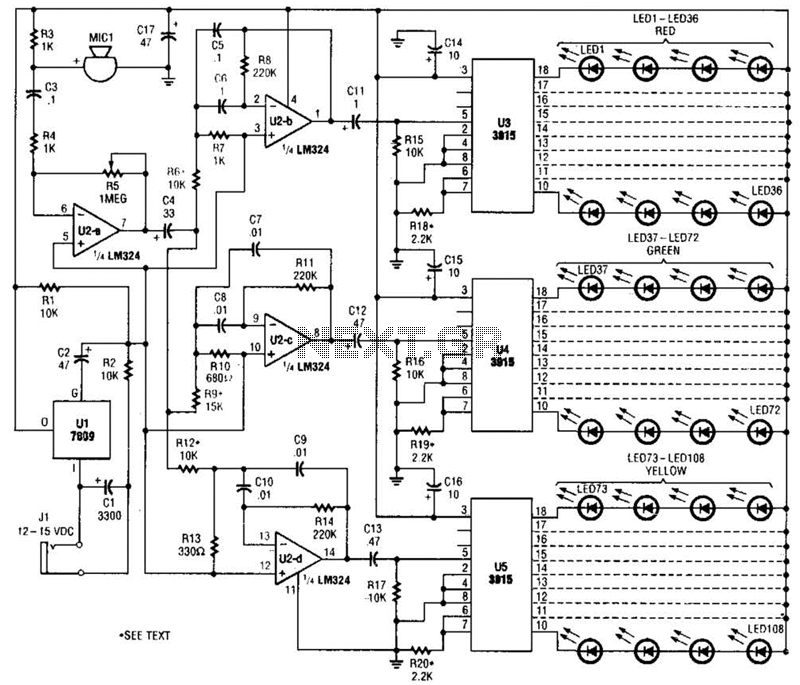
The microphone input, MIC1, is connected through capacitor C3 and resistor R4 to the inverting amplifier U2-a, where the gain of U2-a is adjusted by potentiometer R5. The output from U2-a is passed through capacitor C4 to the remaining...
Warning: include(partials/cookie-banner.php): Failed to open stream: Permission denied in /var/www/html/nextgr/view-circuit.php on line 713
Warning: include(): Failed opening 'partials/cookie-banner.php' for inclusion (include_path='.:/usr/share/php') in /var/www/html/nextgr/view-circuit.php on line 713