
Filters

The helical filter described is a critical component in radio frequency applications, particularly for low-noise receivers. The design focuses on minimizing losses and maximizing signal integrity through careful selection of materials and construction techniques. The use of helical resonators allows for efficient energy storage and transfer, which is essential for maintaining signal quality. The choice of copper wire with appropriate insulation ensures durability and reliability, while the adjustable trimmer capacitors provide fine-tuning capabilities to achieve optimal performance.
In terms of construction, the use of copper-clad printed circuit boards not only provides a sturdy housing for the resonators but also aids in effective grounding and shielding against electromagnetic interference. The dimensions of the enclosure are designed to facilitate the necessary resonator dimensions while ensuring that the entire assembly remains compact. The tuning process, which involves careful adjustments to the resonators and monitoring of the output characteristics, is vital for achieving the desired filter response.
Overall, the helical filter's design and implementation reflect a balance between performance, practicality, and adaptability, making it suitable for various applications in the field of radio communications and signal processing. Proper attention to detail during construction and tuning will yield a filter that meets the stringent requirements of modern RF systems.This option has the advantage that one does not need to change anything in the receiver itself. However, since any filter will give some attenuation of the signal, this will degrade the noise figure of the receiver, and thus limit the weakest signal which could be detected. This is not a big disadvantage as it might seem, since at 20 MHz noise fro m the Milky Way gives a background of about 50 000 K, while the internal noise of the receiver is about 1200 K. If the filter`s attenuation is e. g. 10 dB, the galactic background is at 5000 K, still much above the receiver`s noise. Thus it remains the limiting factor for detection of signals. Another disadvantage may be the large space occupied by the filter: In order to provide a large rejection to unwanted signals, the resonators must be of very low electrical losses, which unfortunately can only be provided by sufficiently large air coils.
The best way to make low loss resonating circuits is to use helical resonators, i. e. the coils are in resonance with the capacitance of their shielding boxes. The filter shown above has two coils which are done from ordinary copper telephone or hook-up wire, about 0. 5 mm diametre, with red plastic insulation, wound on 2. 5 cm diametre plastic tubes. The hot end of each coil is terminated in a small trimmer capacitor. Since the trimmers I have are a bit jumpy when adjusting, I use two trimmers in parallel, each has 12 pF maximum capacitance.
The two resonators are capacitively coupled via the silvered wire which leads from the top of the left hand coil through a hole in the partition and ends as a nearly vertical wire placed close to the top of the right hand coil. The input and output is done by a tap at 1/2 to 3/4 of a turn from the earthy end. The wires seen to bridge the front gap between the side walls are installed to electrically close the box as well as to shield the resonators from external influences.
These wires are initially quite sufficient to close the box electrically while still allowing mechanical access to make adjustments e. g. of the coupling. Sometimes, an improvised close grid of wires can provide adequate shielding, as in the version we used in summer 2003 shown below.
However, if you are in an electronically noisy environment, for instance next to computers, a complete screening is absolutely mandatory - after finishing the design, the filter was covered with a piece of sheet metal soldered over the compartment, and it is now literally watertight! The above sketch shows the schematic structure of a helical filter with inductive coupling via an aperture in the central partition at the earthy ends of the coils.
Instructions how to design filters may be found in the book "Filter design and Synthesis" by A. Zverev. Here are some constructional details of filters I`ve built: The boxes are done from copper-clad printed circuit board; the size should be as large as convenient, but boxes with a square section of 4 to 6 cm, and about 10 cm height give reasonable results. The coil`s diameter should be one half of the width of the box. Most often I use silvered copper wire of 1 mm thickness, but as shown in the filter above, normal copper wire also is useable.
One makes as many turns as possible - ideally, the length of the coil`s wire should be one quarter wavelength, but at 20 MHz that much of wire would not fit in the enclosure. The exact number of turns is not so important, since one will make the resonator resonate on the proper frequency with the trimmer capacitor.
Sometimes, one needs to add a fixed capacitor as well. Having built the two coils, next comes the most essential and critical part: The tuning of the resonators and the adjustment of the input and outputs and the coupling between the resonators. The possibility of displaying the filter curve while sweeping through the frequency is almost indispensible!
One may tune the two coils to resonance by using a dip-meter. But swept frequency mesurement is the only way to adjust the coupling between the coils to the desired critical coupling, with a single maximum, a flat pass band and steep skirts. The input and output are connected to a very low tap on the coils, say to about one turn from the earthy end.
This essentially sets the bandwidth of the filter. If desired, proper measurents of the bandwidth can be made to verify whether the desired value is obtained. For RadioJove applications, one wants to have some 300 kHz bandwidth, so that the receiver`s entire tuning range fits in.
If possible, one should measure the insertion loss, i. e. the attentuation in the centre of the passband. For the filters described here, about 3 dB should be expected. But note that even 10 dB will not severely affect the senstitivity of the receiver, due to the galactic background. 🔗 External reference
Related Circuits
A current differencing transconductance amplifier (CDTA) serves as an active component that can be utilized to create various filter responses. The selection of different filter characteristics is achieved by altering the bias current supplied to the amplifier. The current differencing...
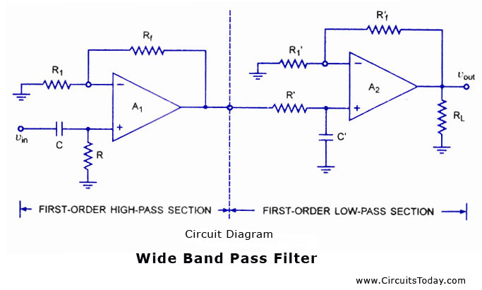
A band-pass filter is a circuit designed to pass signals only within a specific band of frequencies while attenuating all signals outside this range. The key parameters of a band-pass filter include the high and low cut-off frequencies (fH...

Generating sine waves with controlled frequencies over a wide range is challenging when using RC or LC sinusoidal oscillators. However, this can be effectively achieved using a wideband digital square wave oscillator, a counter, and a weighted summing network....
This audio noise filter circuit is a bandpass filter designed for the audio frequency range. It effectively filters out unwanted signals that fall outside the audio frequencies. The circuit consists of two filters: a low-pass filter and a high-pass...
Switched-capacitor filters that are preset for a given bandwidth sometimes do not deliver the bandwidth or Q an application requires. By inverting the clock between two switched-capacitor bandpass filters, such as the MSFS1 from Mixed Signal Integration Corp, you...
Three second-order filters are illustrated: low pass, high pass, and bandpass. Each filter will attenuate frequencies outside their passband at a rate of 12 dB per octave, which corresponds to a reduction of one-quarter of the voltage amplitude for...