
Simple sine-wave generator has no low- or high-pass filters

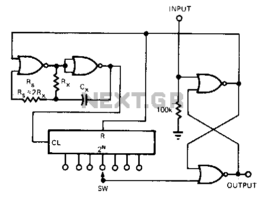
The circuit architecture consists of a digital square wave oscillator that acts as the frequency source, producing a high-frequency square wave signal. The counter IC (IC1) divides this input frequency, generating a series of binary outputs (Q0-Q4). The outputs Q0 to Q3 provide the necessary signals for creating the sine wave's alternating halves, while Q4 serves as a control signal for the EXOR gates, ensuring proper signal inversion.
The inverter (IC2) is crucial for sequencing the input resistors connected to the summing amplifier (IC3). By controlling which resistors are active at any given time, the circuit shapes the waveform. The summing amplifier integrates the weighted contributions from the resistors, where each resistor corresponds to a specific part of the sine wave. The weighted currents at the summing junction are critical; they must be carefully calculated to ensure that the resulting waveform accurately represents a sine wave.
The EXOR gates play a pivotal role in determining the output waveform's phase by inverting the signals based on the control logic provided by Q4. This logic ensures that the output waveform alternates correctly between positive and negative halves, maintaining the integrity of the sine wave shape.
For optimal performance, the circuit requires that the input clock frequency be maintained at 32 times the desired output frequency. This high clock rate allows for a smooth approximation of the sine wave, as the summing amplifier effectively integrates the contributions from each of the 16 segments of the waveform.
Overall, this circuit design provides a versatile solution for generating high-quality sine waves across a broad frequency spectrum, suitable for various applications in signal processing and waveform generation.Generating sine waves with controlled frequencies over a wide range is difficult when using RC or LC sinusoidal oscillators. However, this performance can be simply created using a wideband digital squarewave oscillator, a counter, and a weighted summing network.
Using the circuit shown, a sinusoidal output signal with a 100, 000, 000+:1 frequency range from about 1 MHz to under 0. 01 Hz can be obtained without need for any lowpass or high-pass filters. The circuit consists of two parts. The first part is a counter IC with a controlled inverter (IC2) that sequences the switching of input resistors of the second part ”a summing amplifier (IC3). The EXOR gates are used to invert signals from four of IC1 counter`s outputs (Q0-Q3), depending on logical value at the fifth counter output (Q4).
This operation creates the positive and negative halves of the sine waveform. Each of these halves consists of 24 = 16 parts. The logical values at IC1`s Q0-Q4 outputs produce weightedsymmetrical currents at the summing junction of IC3. The amplifier adds all four weighted currents and generates an output signal with the desired sinusoidal waveform.
Every period of the output signal needs 16 * 2 = 32 periods of input signal, i. e. the frequency of input clock signal must be 32 times higher than the desired frequency of output analog signal: 🔗 External reference
Related Circuits
This circuit is designed for applications where over-current protection is necessary. An example can be found in the model train hobby. Experienced model train enthusiasts understand that troubleshooting a short-circuit can be quite challenging. While it is relatively easy...
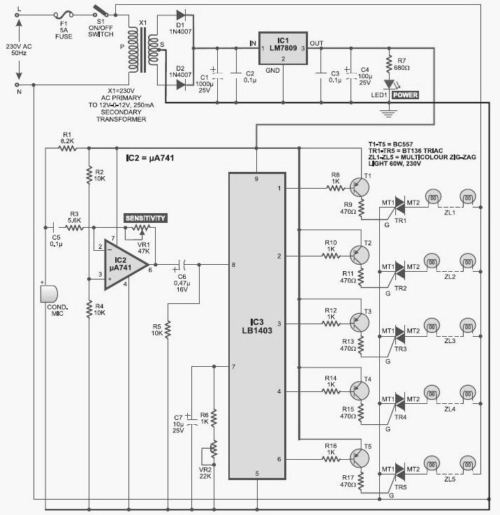
This light chaser circuit, which functions as a music-operated lighting effect generator, consists of five sets of 60W bulbs arranged in a zig-zag configuration. The light chaser circuit is designed to create dynamic lighting effects that synchronize with music, enhancing...
Below 10 MHz, the development of engineering models is relatively straightforward and not significantly influenced by printed circuit board layout. In the VHF range, parasitic circuit elements and unwanted coupling can severely impact efforts to achieve cost-effective performance without...
This tester can be used to check the polarity of any power source, and is therefore very useful when installing automotive equipment, alarm systems or anything else you can think of. Because this circuit is so simple and cheap,...
This CMOS circuit functions as a one-shot time delay switch and a general-purpose timer. It comprises a gated oscillator and a latch utilizing a CD4001 quad 2-input NOR gate, along with a CD4020 14-stage counter. The timing interval, TON,...
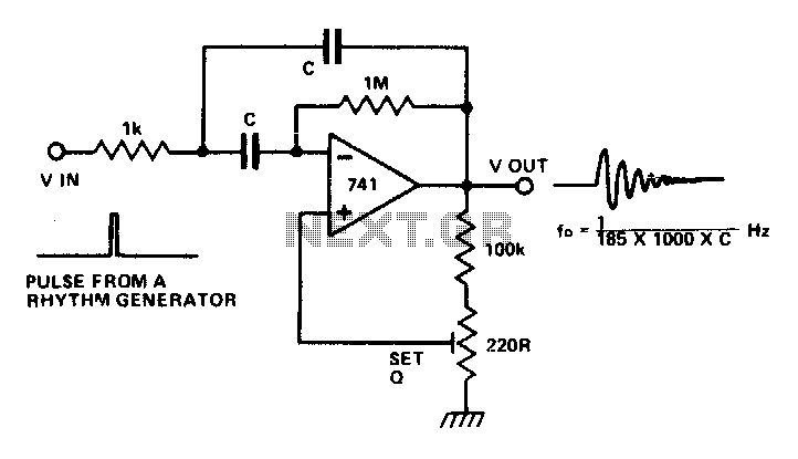
The circuit is a multiple feedback bandpass filter. A brief click (pulse) causes it to resonate at its natural frequency. The oscillations diminish exponentially, closely resembling various naturally occurring percussive or plucked sounds. The higher the quality factor (Q),...