
Fire Alarm Circuit using LDR (Light Depending Resistor)
The fire alarm circuit employs a combination of sensitive components to detect the presence of smoke and heat, activating an alarm signal to alert users of potential fire hazards. The LDR operates on the principle of photoconductivity, where its resistance decreases with an increase in light intensity, which is affected by smoke particles. The NE555 timer, configured in astable mode, generates a continuous square wave output that can be adjusted in frequency by varying the resistors and capacitor connected to it.
Transistors T1 and T2 serve as amplifiers and switches in the circuit. T1 is responsible for detecting changes in voltage at its base, which occurs when the thermistor heats up, indicating a fire. This change in voltage is crucial as it allows T1 to turn on T2, which in turn enables the NE555 timer to produce an audible alarm through T3. The alarm sound is crucial for alerting individuals in the vicinity of the fire.
Capacitor C1 plays a significant role in determining the response time of the alarm. By charging up to the supply voltage, it introduces a delay that allows the system to maintain the alarm state for a predetermined duration, even after the initial trigger condition has passed. This feature ensures that the alarm remains active long enough to alert anyone nearby, providing a critical safety margin.
The inclusion of a diode (D1) prevents unwanted backflow of current that could lead to false triggering of the alarm or damage to the components. Resistor R4 acts as a pull-down resistor to ensure that the NE555 timer remains inactive when not triggered, thus conserving power and preventing false alarms.
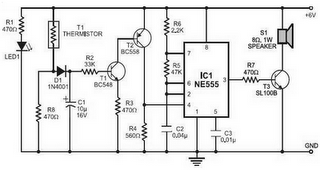
Overall, this fire alarm circuit design showcases a practical application of basic electronic components and principles to create an effective safety device capable of responding to fire emergencies. The careful selection of components and their configuration ensures reliable operation and timely alerts in the event of a fire.Fire Alarm Circuit using LDR (Light Depending Resistor) as ablaze sensor. It warns the user adjoin blaze accidents. It relies on the smoke that is produced in the accident of a fire. Back this smoke passes amid a LED and an LDR, the bulk of ablaze falling on the LDR decreases. This causes the attrition of LDR to access and the voltage at the abjec t of the transistor is pulled aerial due to which the accumulation to NE555 again activated the alarm. The thermistor offers a low attrition at aerial temperature and aerial attrition at low temperature. This abnormality is active actuality for analysis the fire. The IC1 (NE555) is configured as a chargeless active oscillator at audio frequency. The transistors T1 and T2 drive IC1. The achievement (pin 3) of IC1 is couples to abject of transistor T3 (SL100), which drives the apostle to accomplish anxiety sound.
The abundance of NE555 depends on the ethics of resistances R5 and R6 and capacitance C2. When thermistor becomes hot, it gives a low-resistance aisle for the absolute voltage to the abject of transistor T1 through diode D1 and attrition R2. Capacitor C1 accuse up to the absolute accumulation voltage and increases the the time for which the anxiety is ON.
The beyond the amount of C1, the beyond the absolute bent activated to the abject of transistor T1 (BC548). As the beneficiary of T1 is accompanying to the abject of transistor T2, the transistor T2 provides a absolute voltage to pin 4 (reset) of IC1 (NE555).
Resistor R4 is called s0 that NE555 keeps abeyant in the absence of the absolute voltage. Diode D1 stops absolution of capacitor C1 back the thermistor is in affiliation with the absolute accumulation voltage cools out and provides a aerial attrition path. It additionally inhibits the advanced biasing of transistor T1. 🔗 External reference
Related Circuits

This USB to Serial RS232 adapter is highly beneficial in scenarios where a device with RS232 needs to be connected to a computer lacking an RS232 port but equipped with a USB port. Utilizing the FT232BM chip produced by...
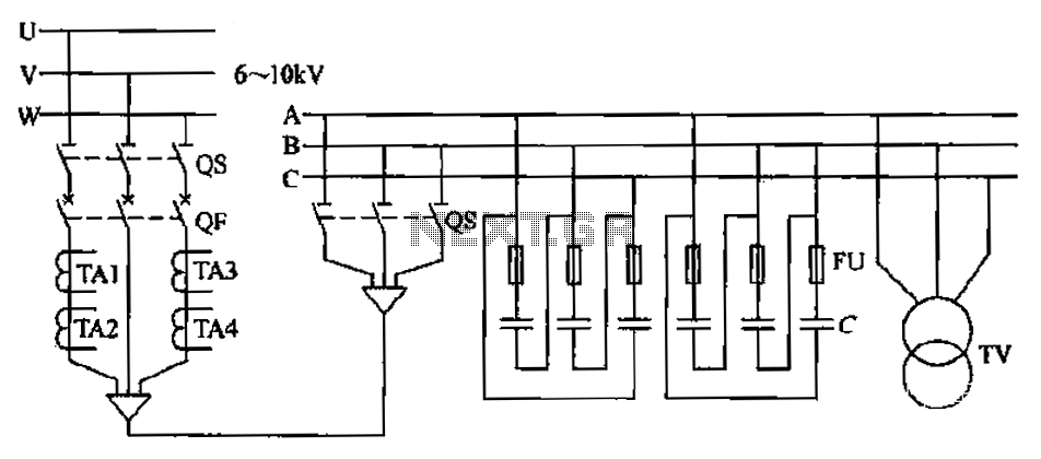
The compensation system is designed to focus on a high-pressure, high-voltage capacitor bank installed in the substation 6-10 kV bus. Compensation can only be implemented in this manner for the 6-10 kV bus before the reactive power on the...
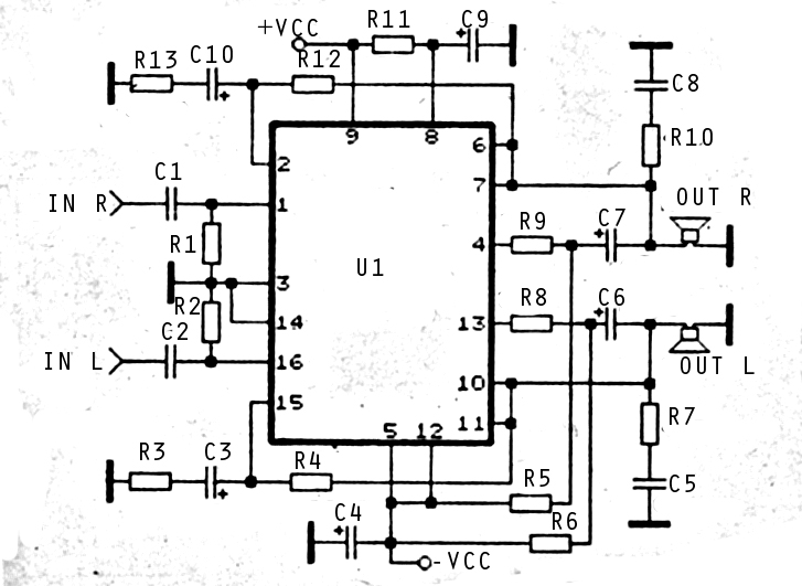
The audio amplifier circuit is highly suitable for home use, particularly with subwoofer or woofer speakers. Commonly referred to as a home amplifier, these audio amplifiers are based on integrated circuits (ICs), specifically the STK series, which includes models...

This electronic schematic can be used to design a simple cellular phone detector circuit capable of sensing the presence of an activated mobile phone from a distance of approximately 1.5 meters. The C3 capacitor should have lead lengths of...

This circuit has the advantage of transferring almost all the energy from the collapsing magnetic field of L2 to C2. In contrast, a typical Joule thief circuit allows some of this energy to return to the battery. This efficiency...

A photocell circuit provides automatic threshold adjustment. Monostable action prevents undesired retriggering of the output. With only one op amp IC, the circuit offers automatic adjustment of its trigger level to accommodate various light sources, changes in ambient light,...