
circuit shows 8x overunity
Warning: Undefined array key "extension" in /var/www/html/nextgr/view-circuit.php on line 468
Deprecated: strtolower(): Passing null to parameter #1 ($string) of type string is deprecated in /var/www/html/nextgr/view-circuit.php on line 468

This circuit utilizes the principles of electromagnetic induction and energy transfer, focusing on the efficient management of energy flow within its components. The core component, L2, acts as an inductor that stores energy in its magnetic field when current flows through it. Upon interruption of the current, the magnetic field collapses, inducing a voltage spike. In this configuration, the energy is primarily directed into capacitor C2, maximizing the energy transfer efficiency.
The resistor VR2 plays a critical role in this circuit by acting as a current limiter. By restricting the flow of current back to the power source or capacitor, it ensures that the energy released during the collapse of the magnetic field is not wasted. This design contrasts with conventional Joule thief circuits, where some energy is typically returned to the source, thereby reducing overall efficiency.
It is important to note that while the circuit demonstrates improved energy transfer characteristics, achieving over-unity (output energy exceeding input energy) remains a theoretical challenge. For over-unity operation, the energy harvested from the collapsing magnetic field must surpass the energy input required to create the magnetic field initially. This requirement raises questions regarding the conservation of energy, as historical data indicates that the energy stored in magnetic fields of coils does not support the possibility of over-unity performance.
In summary, the circuit's design emphasizes energy efficiency through the strategic management of current flow and energy storage, presenting a notable advancement in the functionality of Joule thief circuits while adhering to established principles of physics.This circuit has an advantage in that almost all of the energy in the collapsing magnetic field of L2 is transferred to C2. Where as in a normal Joule thief some of this energy is returned to the battery. This is a result of the resistor VR2 preventing rapid current flow back to the capacitor/battery and thus forcing the energy into C2.
However, i n order to be over unity the energy in the collapsing magnetic field of L2 would have to be greater than the energy used to create the magnetic field. This would conflict with historical experimental data on energy stored in magnetic fields of coils. 🔗 External reference
Related Circuits
This page features a circuit that has twenty open collector outputs that turn on one at a time in a continuous sequential manner. The circuit utilizes the 74LSxx family of TTL integrated logic devices. The circuits are designed to...

The relay power in the linear circuit is derived from a -120 V bias supply, while the transmit keying output from the Kenwood device is +12 V with a maximum current of 10 mA. A critical component of this...
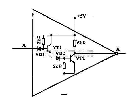
The internal structure of the DTL inverter circuit (M5936P) is composed of inputs with diodes and transistors for signal processing, powered by a +5V supply. When the input terminal A is at a high level (digital 1), diode VDI...
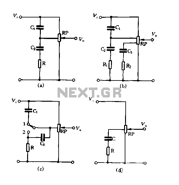
Figure 1.88 illustrates the loudness control circuit utilizing multiple taps on a potentiometer. In Figure (A), the connection is made between the tap and the potentiometer's input, along with the ground. An RC compensation network is employed, where the...
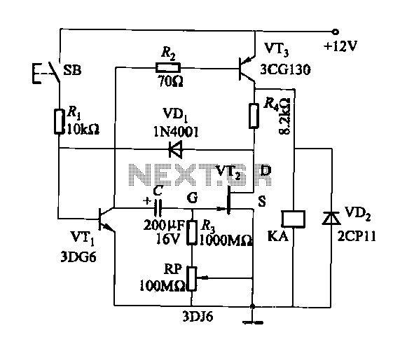
Discharge time relay circuit. The timer utilizes a field effect transistor, providing high timing accuracy and extended timing capabilities. With R3 set to 1,000,000 ohms and C at 200 microfarads, a delay time of 8 hours can be achieved....
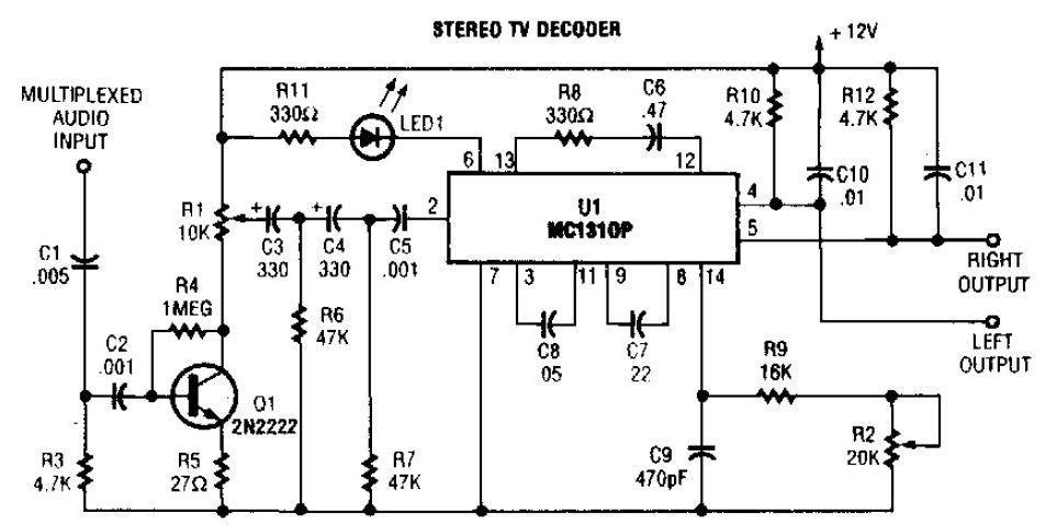
A simple stereo TV decoder circuit built with the MC1310P. Transistor Q1 functions as an audio amplifier, while U1 operates at a 31.5 kHz subcarrier frequency, which is similar to a 38 kHz FM multiplex. The pilot frequency is...
Warning: include(partials/cookie-banner.php): Failed to open stream: Permission denied in /var/www/html/nextgr/view-circuit.php on line 713
Warning: include(): Failed opening 'partials/cookie-banner.php' for inclusion (include_path='.:/usr/share/php') in /var/www/html/nextgr/view-circuit.php on line 713