
Fire Alarm Using Thermistor

The fire alarm system described employs a thermistor (TH1) as the primary temperature sensing element. This NTC (Negative Temperature Coefficient) thermistor decreases its resistance as temperature increases, providing a variable resistance that can be monitored by the circuit. The circuit is designed to activate an alarm when the temperature exceeds a predetermined threshold, indicating the presence of a fire.
The timer IC (IC1), configured as an astable multivibrator, generates a square wave output at audio frequencies. The frequency of oscillation is determined by the resistor values (R5 and R6) and capacitor (C2) connected to the timer IC. Adjusting these components allows for tuning the alarm sound to a desired frequency, ensuring it is loud enough to alert occupants in case of a fire.
Transistors T1 and T2 serve as driving stages for the timer IC. When the thermistor detects increased temperature, it lowers its resistance, causing a voltage change that is fed into the base of transistor T1. This action turns on T1, which in turn activates T2, creating a positive feedback loop that keeps the timer IC in a triggered state. The collector of T1 is connected to the base of T2, ensuring that once triggered, the circuit remains active until reset.
The output from the timer IC (pin 3) is connected to a loudspeaker through transistor T3, which amplifies the audio signal to generate a loud alarm sound. This output serves as an alert mechanism, effectively notifying individuals of the fire hazard.
The circuit's design accommodates a wide range of supply voltages, from 6V to 12V, making it versatile for different applications. This flexibility allows for integration into various fire safety systems, enhancing its utility in residential or commercial settings. Overall, the use of a thermistor in conjunction with a timer IC and transistors provides an effective solution for fire detection and alarm activation, ensuring safety and responsiveness in emergency situations.Many fire alarm circuit is published in different website. But, here in this website is a simple and inexpensive project of fire alarm using thermistor. where thermistor is used astemperaturesensor of fire alarm. Working principle of thermistor is same as LDR (change their resistance with change in heat where LDR change their resistance with change in light fall on it). The whole circuit of fire alarm using thermistor is build and fabricated around thermistor (TH1) and timer IC (IC1) with its driver transistor. The timer IC (IC1) used in this circuit is as astable multivibrator oscillator used to oscillate in audio frequency band.
The two transistor T1 and T2 used to drive the timer IC (IC1). The output from pin 3 of IC1 is fed to loudspeaker through transistor T3 to generate sound. The value of resistor (R5 and R6) and capacitor (C2) determines the frequency of IC2. The low resistance path of extend positive voltage to the base of transistor is provided when the thermistor TH1 become hot. Further collector of transistor T1 is connected to base of transistor T2 provides positive voltage to reset pin 4 of IC1 for reset.
Fire alarm using thermistor circuit works on wide range of input power supply voltage i. e. 6v to 12V. 🔗 External reference
Related Circuits

A sequential timer circuit device is utilized in various applications for initializing conditions during start-up or for activating test signals in sequences, such as in test equipment devices. The circuit diagram below illustrates a sequencer circuit with potential applications...

At the initial state, all pin 15 connections are grounded, causing resistor R0 to be energized. A 555 multivibrator generates a clock signal to IC1, activating the outputs from R0 to R8. This basic circuit can be employed to...

The voltage at the anode and cathode of the diodes is checked to determine whether they are conducting. There is confusion regarding the current source and how to determine the state of the diodes for input combinations (00, 01,...
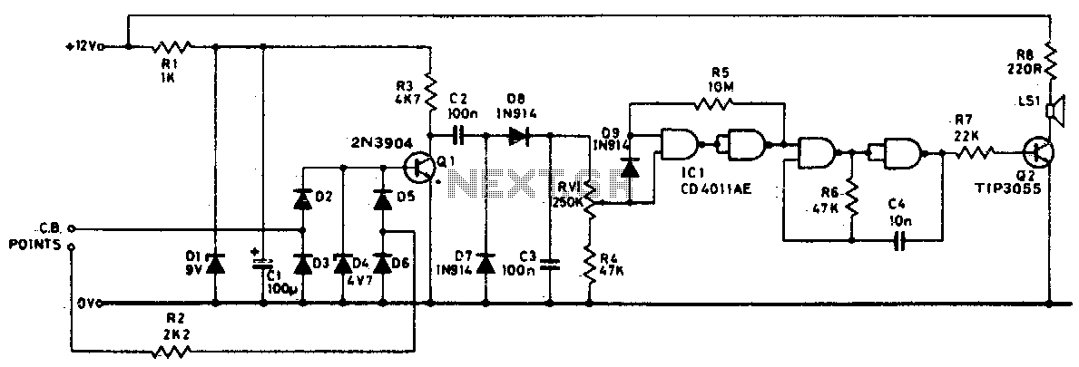
Pulses from the distributor points are passed through a current-limiting resistor, rectified, and clipped at 4 volts. Through Q1 and the diode pump, a DC voltage proportional to engine RPM is presented to RV1. The sharp transfer characteristic of...
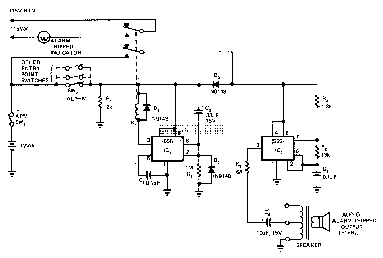
This circuit cannot be shut off for 10 to 60 seconds, even if the trip condition is immediately removed. It draws no standby power from the battery and is self-resetting. The described circuit operates under a delay mechanism that...

A PB-12N23PW-05Q buzzer is being used with an ATmega 162 microcontroller. Direct connection to the microcontroller pin is not feasible due to the maximum sourcing capability of 20 mA as stated in the ATmega 162 datasheet, while the buzzer...