
Logic gate using current source and diodes
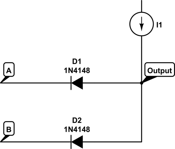
The circuit in question appears to implement a NAND gate configuration using diodes. A NAND gate outputs a low signal only when all its inputs are high, which aligns with the observed behavior in the simulation. The diodes serve as the primary switching elements, controlling the flow of current based on the input states.
In the circuit, the anode of each diode is connected to the respective input (A or B), while the cathodes are tied together and connected to the output. When both inputs are high (logic level 1), both diodes conduct, allowing current to flow through to ground, resulting in a low output. Conversely, if either input is low (logic level 0), at least one diode becomes reverse-biased, preventing current flow and thus maintaining a high output.
The analysis of the current source is critical, as it affects how the diodes operate. In this context, replacing the current source with a high-value resistor connected to a positive voltage (e.g., +5V) simplifies the analysis. The behavior of the circuit can be assessed by varying the resistor's value and observing the output voltage across the load.
To further explore the implications of the diode's forward conduction characteristics, consider the impact of a resistor in series with a diode. As the resistance increases from a very low value (approaching 0 ohms) to a significantly high value, the voltage drop across the diode will change. Initially, with a low resistor, the diode will conduct, and the output voltage will be close to 0V. As resistance increases, the voltage drop across the diode will stabilize, and the output voltage will approach the supply voltage when the diode is reverse-biased.
This thought experiment highlights the importance of understanding the diode's operating region and the influence of external components on circuit behavior. By systematically analyzing the circuit under different input conditions and component values, one can derive a comprehensive understanding of the NAND gate's functionality and the role of diodes in digital logic circuits.You check the voltage at the anode and cathode of the diodes and determine whether or not it is conducting. With a current source I am kind of confused on what to do. I can`t determine the state of the diodes for a given input combination (00, 01,10, 11) because I don`t know the voltage at the anode of the diodes.
I have simulated the circuit using LTSpice and it seems like the output is high when both A and B is high. If both A and B are low or if one of A and B is low, the output is low. Why How do you solve this kind of circuit How is a current source usually dealt with in this case Douglas Edward Jun 15 `13 at 14:04 You have concluded it is a NAND gate and I agree. Do you understand the forward conduction characteristics of a diode This will help you, and if you are uncertain by the current source just imagine it is a high value resistor connected to (say) +5V Andy aka Jun 15 `13 at 14:26 I have managed to figure out 00, 01, 10.
If any one of the input is low and the output is high, diode will be forward biased and act as a short, and there will be a contradiction of voltage levels. Therefore the output has to be low if any of the input is low. Now for the 11 case I don`t see how to reason since both cases (output 1 and 0) seem possible. Douglas Edward Jun 15 `13 at 15:40 Maybe a thought experiment helps If you consider a single diode, in series with a very low resistor, say 0$Omega$ what is the output voltage in that case Then slowly increase that resistor 1$Omega$, 10$Omega$, .
what happens to the output in that case What happens if you increase the resistor even further (to $infty$) jippie Jun 15 `13 at 16:03 🔗 External reference
Related Circuits
A small servo tester for modeling can be very useful in various situations for those who frequently work with servos. The primary function of a servo tester is to produce a pulsing signal with a positive pulse width that...
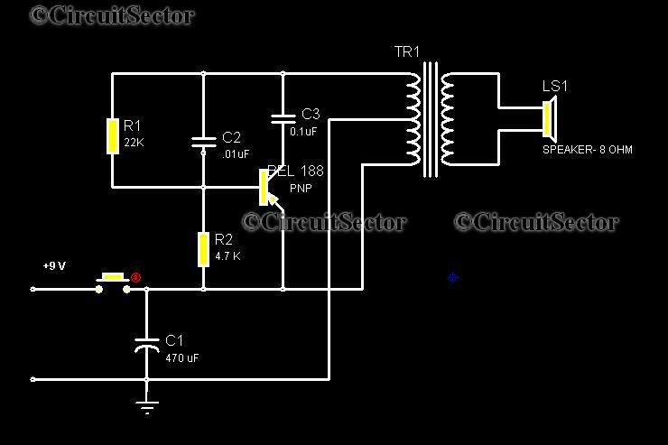
This circuit is a low-cost, one-touch doorbell using a Bel 188 transistor. It is likely one of the most economical bell circuits that can be constructed. The core component of this circuit is the output transformer from a push-pull...

The XTR110 features an internal voltage reference that can output a current of 10mA. By incorporating an external NPN transistor, designated as QREF, the output current capability can be increased. When the VCC voltage reaches 40V, a 2N3055 transistor...

Microcontrollers (MCUs) are versatile integrated circuits (ICs) that enhance the functionality of electronics, robotics, and various other projects. Microcontrollers serve as the brain of embedded systems, providing control, processing, and communication capabilities in a compact form factor. They typically consist...

If the robot is positioned on the black line, it will continue moving forward. However, if it veers off the line and enters a white area, it will assess whether to correct its path to the left or right,...
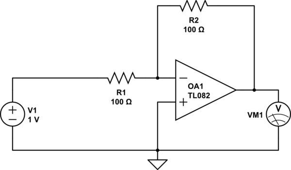
Considering a simple circuit as illustrated below, when the voltage source activates suddenly (changing from 0V to 1V), current will flow through the resistor R1. Assuming an ideal operational amplifier (op-amp) that draws no current, and an ideal voltmeter...