
extended counter using cd4017
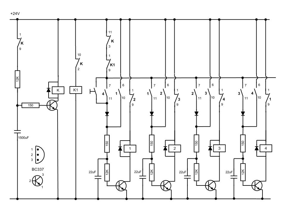
This circuit utilizes a 555 timer configured in astable mode to produce a continuous clock signal. The output from the 555 timer (IC1) is connected to a series of output pins (R0 to R8), which can be used to control various devices or components in the circuit. The initial grounding of pin 15 ensures that the circuit remains in a stable state until the button is pressed.
When the button (P) is activated, it creates a path for current to flow through resistors R1 and R2, which serves to limit the current to the base of transistor T1. This action turns on T1, allowing current to flow from the collector to the emitter, effectively energizing the relay coil. As the relay is activated, it can switch larger loads or control other circuits.
Additionally, the capacitor connected in the circuit plays a crucial role in timing and stabilization. It charges through the resistors, and once a certain voltage threshold is reached, it can influence the behavior of the circuit, such as providing a delay or smoothing out voltage fluctuations.
In summary, this simple yet effective circuit design demonstrates how a 555 timer can be employed to control a relay through a button press, utilizing basic components such as resistors, a transistor, and a capacitor to achieve desired functionality. Proper component selection and configuration are essential to ensure reliable operation and performance of the circuit.At the start condition all pin 15 are connected to the ground, so R0 is energized. A 555multivibrator sendsthe clock signalto IC1, which activates the outputs from R0 to R8. This simple circuit can be utilized to drive a monostable relay through a single button switch. At the start condition the relay does not work. When I press the button (P) T1 is energized through R1 and R2, and the capacitor charges. The coil is jumped by 🔗 External reference
Related Circuits
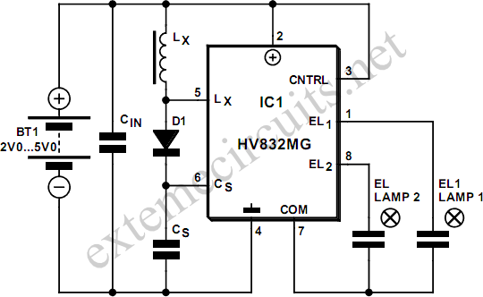
An EL lamp is a solid-state, low-power, uniform area light source. Due to its thin profile (as thin as 0.3 mm) and versatility in size and shape, EL lamps are ideal for providing backlighting for LCD displays, membrane keypads,...
The SP6691 circuit is designed to provide a high output voltage using a lower voltage boost regulator by incorporating a charge pump circuit. This configuration can convert a standard 30V boost regulator into a 60V boost regulator if necessary....
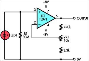
This circuit demonstrates the use of a standard LED as a light sensor by utilizing the photovoltaic voltage generated across the LED when it is exposed to light. LEDs are cost-effective alternatives to photodiodes and include a built-in filter...
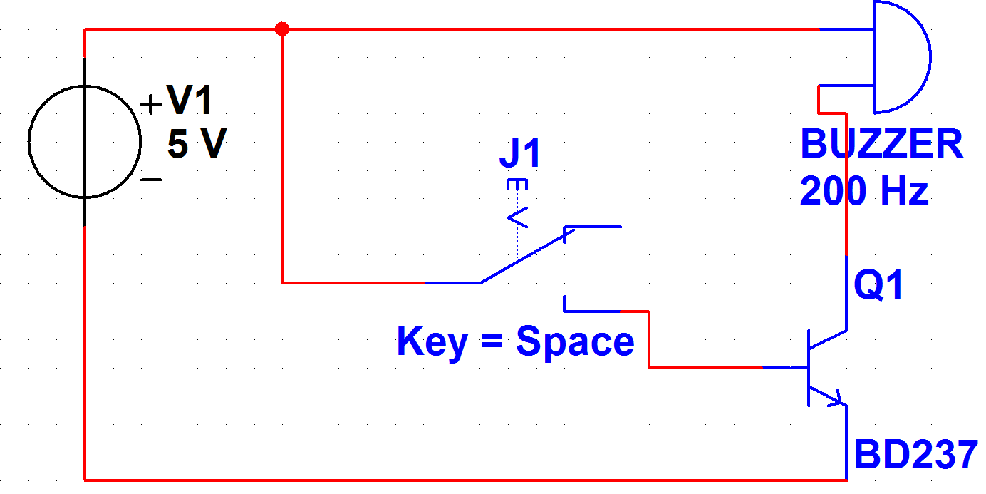
A PB-12N23PW-05Q buzzer is being used with an ATmega 162 microcontroller. Direct connection to the microcontroller pin is not feasible due to the maximum sourcing capability of 20 mA as stated in the ATmega 162 datasheet, while the buzzer...
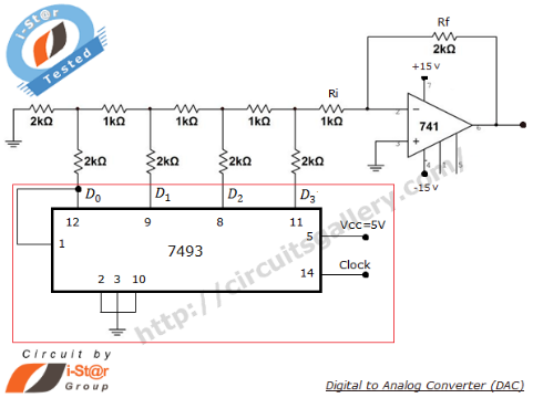
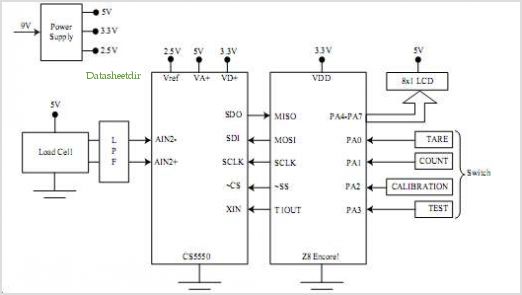
A Digital to Analog Converter (DAC) is utilized to produce an analog voltage that corresponds to input digital data. Binary data can be transformed into its analog equivalent using an R-2R ladder network combined with a summing amplifier, which...
Automated instrumentation wiring using interference filters for the inverter is not as effective for harmonic processing. When operational, it will radiate a strong field strength due to high amplitude electromagnetic waves. If the meter is installed in the automation...