
fireworks controller circuit
The circuit design utilizes a 12V battery pack as the primary power source, which is critical for driving the ignitors and lighting the LEDs. The wooden planks serve as a structural support for the circuit elements and provide a means to secure the nails, which act as conductive points for the wrapped speaker wire. The speaker wire connections to the ignitors allow for effective control of the ignition process, enabling the user to activate the ignitors easily.
The MDF base serves as a practical platform for the electronic components. The careful arrangement of push-buttons and LEDs ensures that the user interface is intuitive and accessible. The use of a drill press for the push-button holes and a hand drill for the LED holes indicates a methodical approach to component placement, which is essential for maintaining functionality and ease of use.
The Dremel tool's application for creating recesses around the button holes highlights the importance of precision in electronic assembly. This modification allows for a more secure fit for the push-buttons, ensuring they are flush with the surface of the MDF, thus enhancing the overall user experience.
The connection of the green LEDs to the primary switch demonstrates a straightforward method of integrating visual indicators into the system. The use of jumpers simplifies the wiring process, although a printed circuit board (PCB) could have provided a more refined solution for future iterations of the design. The inclusion of resistors in series with the LEDs is a standard practice to limit current and prevent damage to the LEDs.
The assembly of the negative terminals and their connection back to the battery is crucial for establishing a complete circuit, ensuring that all components have a common ground reference. The additional 12V LED module serves a dual purpose: it provides visibility for the user while connecting the ignitors and acts as a power indicator, enhancing the functionality of the overall design.
Overall, the circuit demonstrates a practical approach to electronic assembly, prioritizing functionality and ease of troubleshooting while acknowledging the limitations of the construction materials and techniques employed.A 12v battery pack from a PowerWheels(r) car and two planks of wood with several nails punched through each. The nails were each wrapped with a couple turns of speaker wire that ran out to his ignitors, and the other leg came back to a central positive terminal that connected back to the battery.
Not super elegant, but very effective and easy to troubleshoot and control. First off I started with a blank piece of 1/4" MDF I purchased from Home Depot. This served as the base board for the electronics. I decided on a layout for the controls, and then using my drill press and my eyeballs I put the 24 holes for the push-buttons and then used a hand drill for the LED holes. I then used my Dremel tool with a router bit to free hand the slots for the speaker terminal connections.
I am not a carpenter, nor to I claim to have any sort of artistic capability. this part is utilitarianism at its best. It was at this point that I *noticed* my MDF was too thick for the buttons and switches to mount to without modification. so at this point I broke my Dremel back out and cut recesses around EVERY SINGLE button hole to reduce the thickness from 1/4" down to around 1/8".
This was where I lost about 2 hours on my build, because these recesses had to be done free-hand, and it generated copious amounts of dust. Then I started mounting components. I started with the push-buttons and then the LEDs. The push-buttons had nuts to hold them down, and for the LEDs I just used a touch of super-glue right at the edge and it worked great.
The speaker terminals and other switches were very simple to mount. This left me with a very pretty front panel (ignore the fact that I can`t measure and things are a bit crooked). From the primary switch (key-switch) tie in each green LEDs long leg (positive). I used simple jumpers for this. I thought about etching up a PCB for this purpose, and I would if I had a little more time, but for this prototype I just jumped them all together.
From the short leg of the green LED I ran the two 470ohm resistors in series, then tied that to the red side of the speaker terminal. I then tied all of the negative speaker terminals together and tied that back to the negative side of the battery.
I also tied in a 12v LED module into the key ignition so that we could have a little light while hooking the ignitors up, plus it adds a pretty blue glow and also serves as a "power" indicator. 🔗 External reference
Related Circuits
This AC to DC power supply can output 5A in continuous operation and 12A peak current. This type of DC power supply uses a PCB, allowing for two case types. The described AC to DC power supply is designed to...
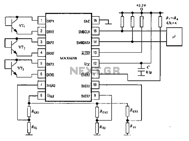
The circuit illustrated in the figure involves the MAX6698 maximum temperature sensor, which utilizes three transistors (VT1 to VT3) and three thermistors (RT1 to RT3). An internal reference voltage source is connected through resistors UREF REX1 to REX3, providing...
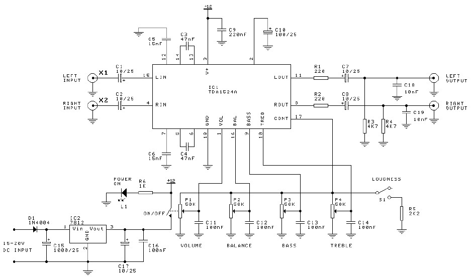
Preamplifier and tone control circuit based on the TDA1524A. The tone control circuit module is included in this preamplifier circuit, allowing for direct connection of the output channels to a stereo power audio amplifier circuit. This RIAA stereo preamplifier...

This circuit produces a soft turn-on for halogen lamp filaments upon powering up. The MOSFET used is a BUZ10, which has a resistance of 0.2 ohms. Resistors R1, R2, and capacitor C1 set the turn-on rate, while diode D1...
Logic testers are simple yet very useful devices for testing digital circuits. A logic probe can be designed in various ways. Logic testers, commonly referred to as logic probes, are essential tools in the field of digital electronics. These...
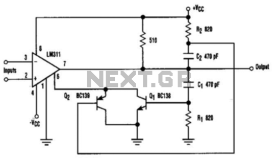
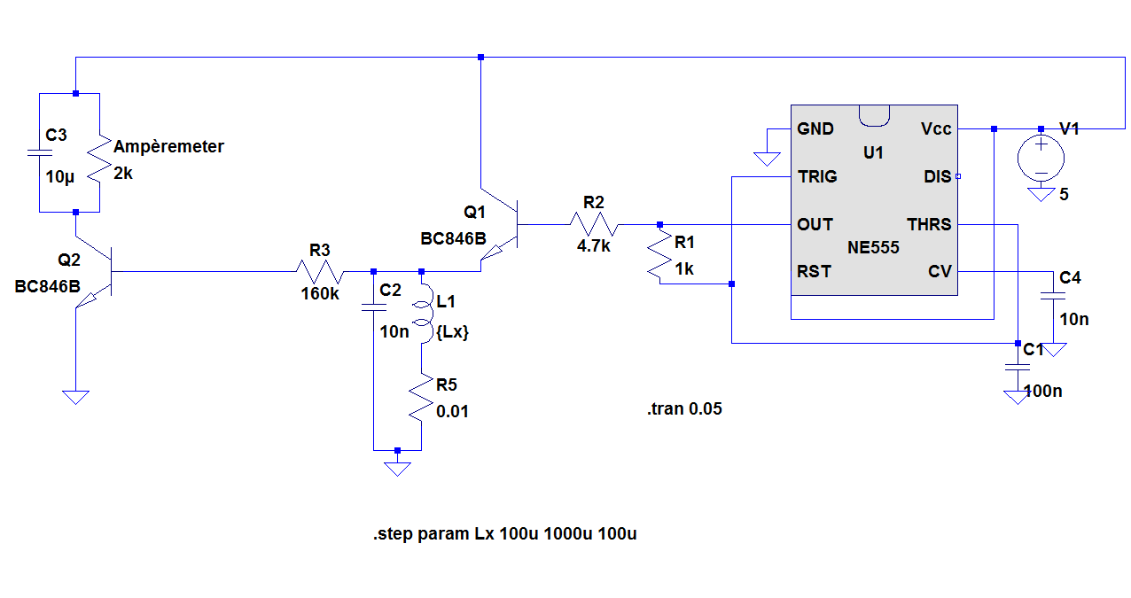
When the comparator's output transitions from low to high, the rising edge of the output pulse, differentiated by the Cl/Rl chain, activates Ql. This action blocks the comparator via its strobing input and maintains its output state for a...