
Halogen Lamp Protector Circuit

The circuit employs a BUZ10 MOSFET to control the power delivered to halogen lamp filaments, allowing for a gradual increase in brightness rather than an abrupt illumination. This soft start feature is particularly beneficial for extending the lifespan of the halogen lamps, as it reduces thermal stress on the filaments during power-up.
Resistor R1 and resistor R2 form a voltage divider that influences the gate voltage of the MOSFET, effectively controlling the turn-on time. The time constant for the turn-on process is determined by the values of R1, R2, and the capacitance of C1. A larger capacitance or higher resistance values will result in a slower increase in voltage at the gate, leading to a softer turn-on.
Capacitor C1 plays a crucial role in the timing of the turn-on process. When power is applied, C1 charges through the resistors, gradually increasing the gate voltage until it reaches the threshold voltage of the MOSFET, causing it to turn on. The diode D1 is connected in parallel with C1 and ensures that when the power is turned off, C1 discharges quickly, allowing the MOSFET to turn off rapidly and preventing any residual voltage that could keep the lamp glowing.
The design of this circuit is essential for applications where a sudden surge of current could damage sensitive components or reduce the lifespan of the halogen lamps. By utilizing the BUZ10 MOSFET, which has a low on-resistance of 0.2 ohms, the circuit minimizes power loss and heat generation during operation, enhancing efficiency and reliability. Overall, this soft turn-on circuit is a practical solution for controlling halogen lamps in various lighting applications. This circuit, produces a soft turn-on for halogen lamp filaments upon powering up. MOSFET used is a BUZ10, which has 0.2 Rm on. Rl, R2, and CI set the turn-on rate and D1 discharges CI at turn-off. 🔗 External reference
Related Circuits
This circuit gradually switches the internal lights of a car on and off. The delay time can be adjusted by changing the values of the 10k and 4.7M resistors, as well as the capacitor. The circuit operates by utilizing a...
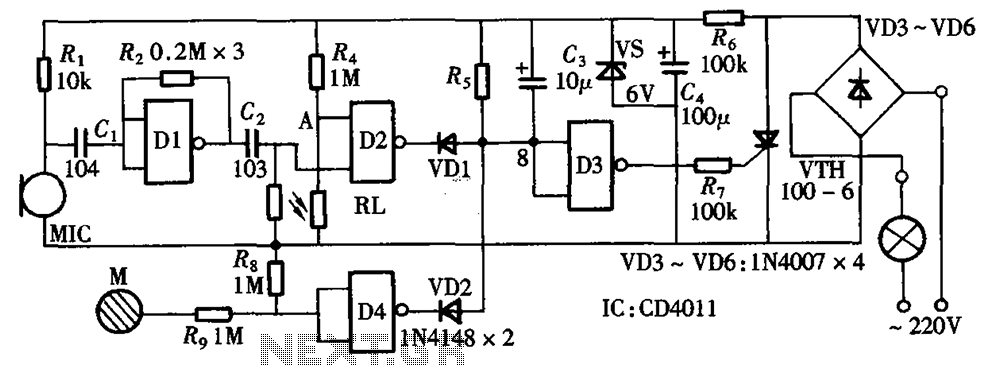
The circuit integrates sound and light control with touch functionality, creating a fully operational delay section light switch circuit. It consists of light control, voice circuits, and a touch control circuit, all triggered by a thyristor switch. The described circuit...
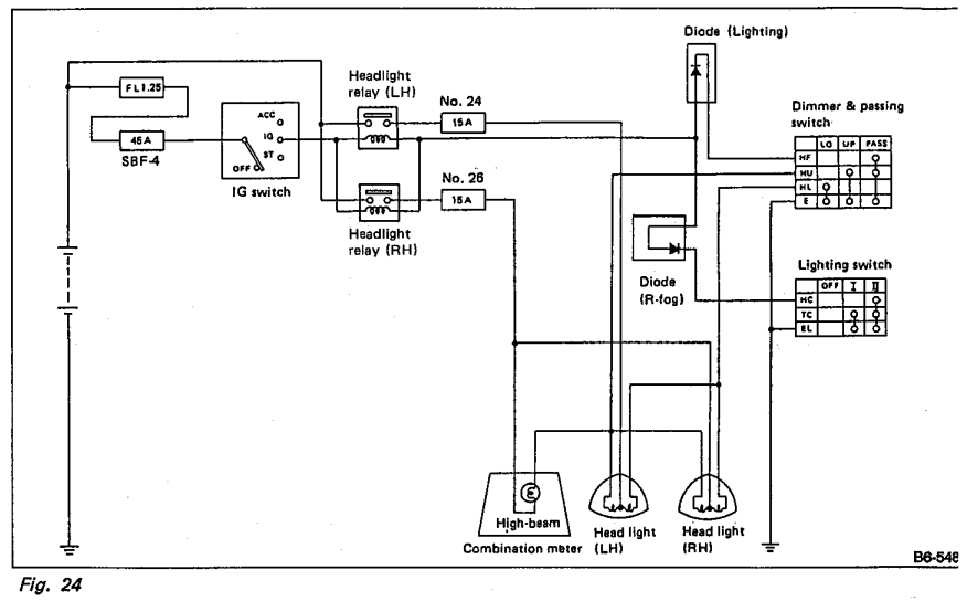
Understanding the headlight wiring in a car involves examining the purpose of two diodes in the circuit diagram. The circuit allows for two independent methods of activating the light relays: through the light switch or by flashing the high...
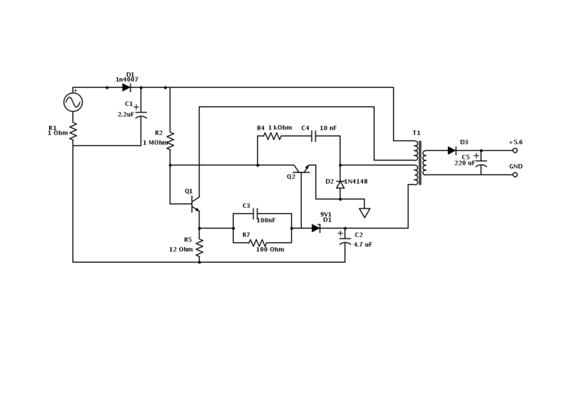
An old Nokia phone charger with a 5.6 V output was modified to provide 12 V by changing the Zener diode from a 9.1 V to a 16 V component. The circuit is mostly understood, but clarification is needed...
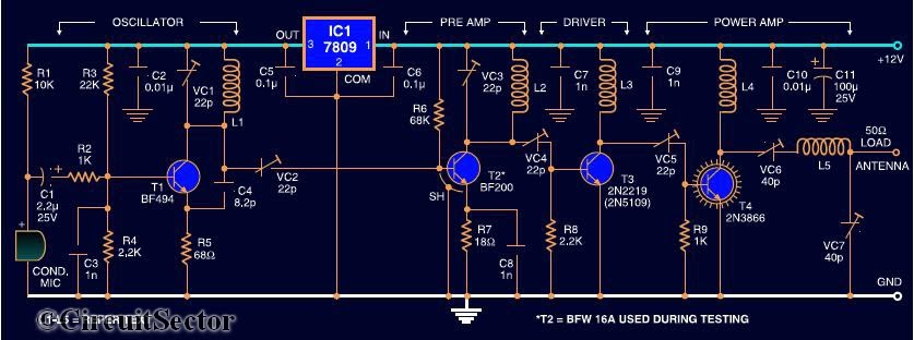
Here is the circuit diagram of a four RF stage FM transmitter. The stages include a very high frequency (VHF) oscillator built around the HF transistor BF494, a pre-amplifier using the BF200 transistor, a driver transistor 2N2219, and a...
To measure the input impedance of an unknown circuit, first set the signal generator to a current source with a magnitude of 1 amp. A shunt resistor of 100 megohms is also required. This setup is beneficial for measuring...