
Temperature Sensor MAX6698 7-Channel Smart consisting of circuit diagram
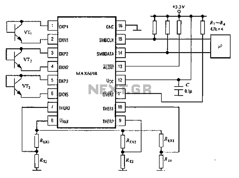
The MAX6698 is a maximum temperature sensor designed for precision thermal monitoring. The circuit operates by utilizing three thermistors, which are resistive temperature devices that change resistance based on temperature variations. Each thermistor (RT1, RT2, RT3) is connected to a corresponding transistor (VT1, VT2, VT3) that acts as a switch to control the output based on the temperature readings.
The internal reference voltage is critical for maintaining the accuracy of the temperature sensing. The resistors (REX1, REX2, REX3) connected to the thermistors ensure that the thermistors are powered correctly, allowing them to provide reliable temperature measurements. The voltage drop across each thermistor is monitored and supplied to the THER pins, which are inputs to the MAX6698, enabling it to determine the maximum temperature among the three sensors.
The choice of transistor models (CMPT3904, SST3904, KST3904-TF, SMBT3904, and FMMT3904CT-ND) is essential for ensuring that the circuit can handle the required switching characteristics and power levels. These transistors are known for their low saturation voltage and fast switching capabilities, making them suitable for temperature sensing applications.
In summary, this circuit configuration effectively utilizes the MAX6698 in conjunction with thermistors and transistors to achieve accurate temperature monitoring and control, suitable for various applications where thermal management is critical. Proper selection of components and careful attention to the circuit design will enhance the performance and reliability of the temperature sensing system. Circuit shown in Figure: MAX6698 maximum temperature with three transistors (VT1 ~ VT3) and three thermistors (RT1 ~ RT3). The internal reference voltage source via a resistor UREF REX1 ~ REX3 were given three thermistor power supply, the voltage drop across the thermistor respectively supplied THER1 ~ THER3 pins. Temperature transistor can be used CMPT3904, SST3904, KST3904-TF, SMBT3904, FMMT3904CT-ND models.
Related Circuits
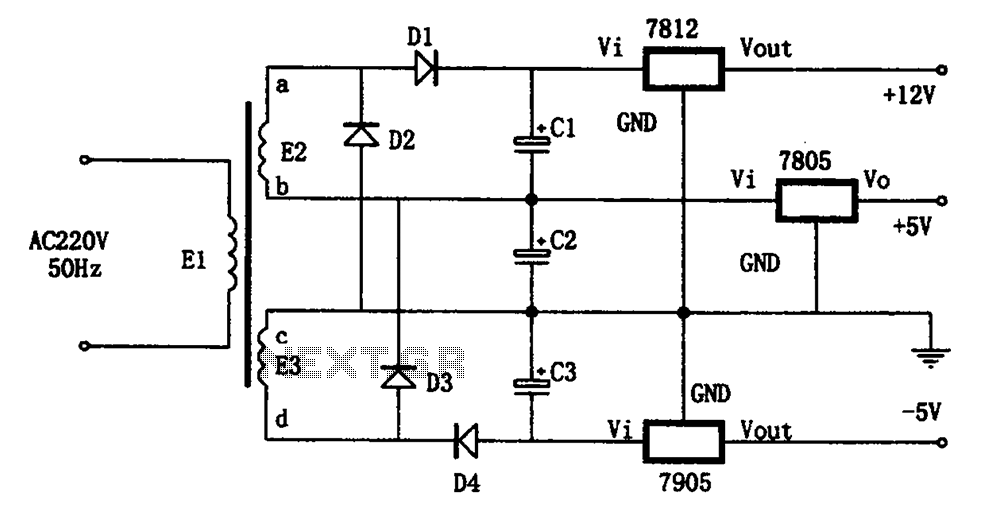
The circuit illustrated in the figure represents a specialized power supply configuration. It is straightforward in design and can be constructed using two identical secondary windings to generate three distinct DC voltage outputs: +5V, -5V, and +12V. The circuit...
A distortion circuit is being developed utilizing a single 12AU7 tube configured as a diode. The design is acknowledged as basic, intended primarily for the purpose of adding distortion effects. The proposed circuit leverages the 12AU7 vacuum tube, which is...
Time delays ranging from 0 milliseconds to over three minutes can be achieved with this circuit without the need for tantalum or electrolytic capacitors. The timing interval begins when power is applied to the circuit. At the conclusion of...

When connecting this element in a voltage divider configuration, a high and low signal can be generated based on the amount of light detected by the sensor. An NPN transistor configured as an inverter further filters this signal to...
Many amplifiers have phono inputs for connecting record players to the amplifier. Phono input is designed to take a up to few millivolt signal from phono pickup and amplify it. The amplifier stage does also some equalization based on...
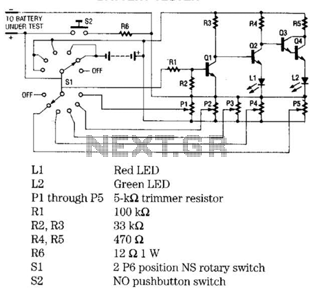
The battery tester utilizes four transistors and two LEDs to indicate the status of any battery being tested. Transistors Q3 and Q4 are configured in a Darlington arrangement, providing extremely high gain. LED L2 illuminates when a small positive...
Warning: include(partials/cookie-banner.php): Failed to open stream: Permission denied in /var/www/html/nextgr/view-circuit.php on line 713
Warning: include(): Failed opening 'partials/cookie-banner.php' for inclusion (include_path='.:/usr/share/php') in /var/www/html/nextgr/view-circuit.php on line 713