
Five reversing operation of the reverse brake circuit

The automatic round-trip plug braking circuit is designed to enhance safety and reliability in applications where precise control of electrical devices is essential. This circuit ensures that the operation of the primary switches (SQ1 and SQ2) is safeguarded against unintended disconnections or faults that may arise during operation.
In this design, the primary switches are critical for controlling the flow of electrical current. However, to mitigate the risk of accidental activation or failure, the inclusion of limit switches S03 and S04 serves as an additional layer of protection. These limit switches are strategically positioned to monitor the operational state of the primary switches. If either switch SQ1 or SQ2 experiences a fault condition, the limit switches will activate and interrupt the circuit, thereby preventing potential hazards.
The circuit operates by using a combination of relays and limit switches that are interconnected in a manner that allows for automatic resetting after a fault condition has been cleared. This functionality is crucial in applications where continuous operation is necessary, and any downtime must be minimized.
The overall design emphasizes robustness and safety, ensuring that the circuit can handle unexpected conditions without compromising the integrity of the system. The use of additional protection limit switches not only enhances the reliability of the circuit but also increases the overall lifespan of the components involved, making it a suitable choice for various industrial applications. Circuit shown in Figure 3-132. The line is automatically round-trip, plug braking circuit. In order to prevent or limit switch SQl offside SQz malfunction caused the accident, two increased protection limit switches s03 and s04.
Related Circuits
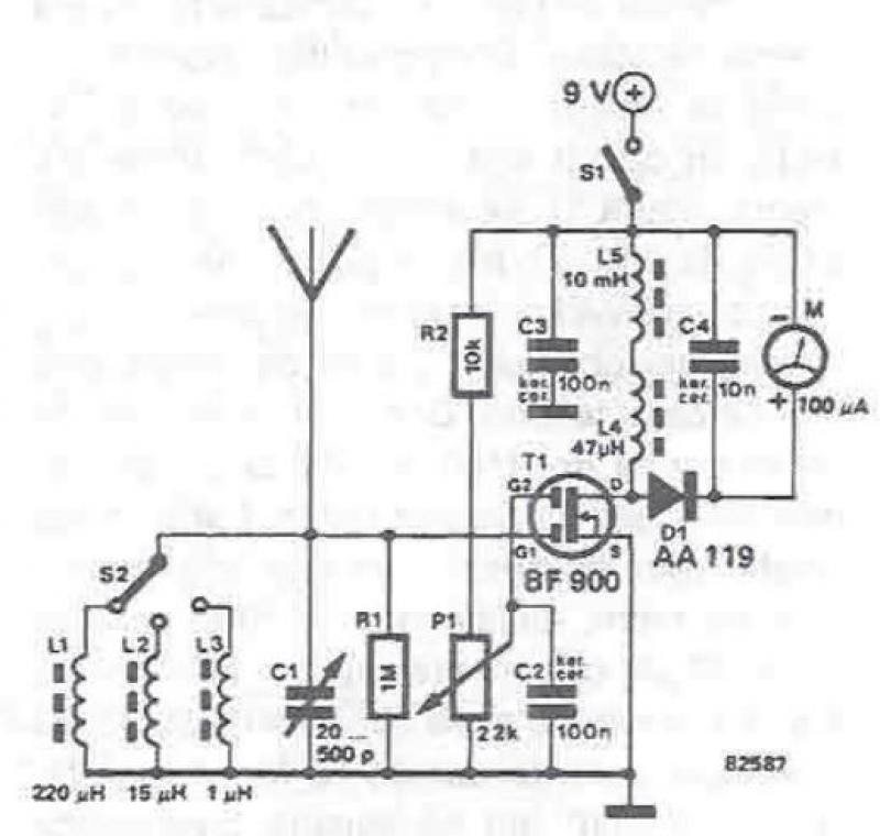
An RF field detector circuit suitable for measuring and verifying the power of antennas and transmitters can be constructed using transistors and common electronic components. This circuit employs a radio frequency transistor, specifically a MOS-FET with two gates. The...
One cannot expect high performance from a basic detector-based meter. Its sensitivity is merely sufficient to provide a fundamental understanding of the power output that the transmitter can achieve. The detector-based meter operates on a straightforward principle where it measures...
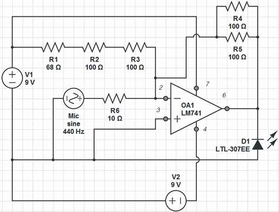
Red = V+, Black = V-, Green = GND, Yellow = Mic Input, Orange = LED Output. The op-amp used is an LM741, which is intended to adjust the peak brightness of the LED based on the ambient sound...

The LM1458 integrated circuit (IC) is utilized to amplify the difference in the left input signal (L), resulting in a surround sound effect. The left signal is coupled through capacitor C2 and resistor R1 to pin 5 of IC1...
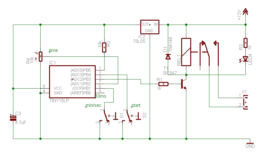
The time can be set using a potentiometer ranging from 1 minute to 1023 minutes, approximately 17 hours. A pushbutton initiates the timing process, activates a relay, and the timer will deactivate the relay once the set time has...

This versatile 741 operational amplifier module can be utilized to create a dark detector using a light-dependent resistor (LDR), a phototransistor, and a photodiode. The amplifier is configured in inverting mode, where it compares the voltage change at pin...
Warning: include(partials/cookie-banner.php): Failed to open stream: Permission denied in /var/www/html/nextgr/view-circuit.php on line 713
Warning: include(): Failed opening 'partials/cookie-banner.php' for inclusion (include_path='.:/usr/share/php') in /var/www/html/nextgr/view-circuit.php on line 713