
op amp Trouble transferring schematic (working) to actual circuit (not working)
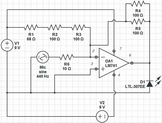
The circuit involves an LM741 operational amplifier configured to modulate the brightness of an LED based on sound input from a microphone. The microphone, designated as the Yellow input, serves as a transducer that converts sound waves into an electrical signal. The output of the microphone is fed into the non-inverting input of the op-amp, while the inverting input is connected to a reference voltage, likely derived from a voltage divider or a fixed reference.
The power supply connections are clearly defined, with Red representing the positive voltage (V+), Black for the negative voltage (V-), and Green for the ground (GND). The op-amp's output, which drives the LED (Orange output), should theoretically vary in response to the sound level detected by the microphone. However, the circuit's performance is hindered by the high impedance of the microphone, which can lead to significant voltage drops and incorrect biasing conditions for the op-amp.
To ensure proper functionality, it is crucial to consider the input impedance of the op-amp relative to the microphone's output. If the microphone's DC resistance is too high, it will prevent the op-amp from achieving the necessary voltage levels to drive the LED effectively. This misalignment can lead to an output voltage that does not correspond accurately to the ambient sound levels, resulting in the observed malfunction.
In practical applications, it is advisable to use a buffer stage between the microphone and the op-amp to mitigate impedance issues. A buffer can provide the necessary current drive while isolating the microphone from the load presented by the op-amp. Furthermore, careful selection of resistors in the feedback loop of the op-amp will help to set the gain appropriately, ensuring that the output voltage accurately reflects the sound levels and allows for proper LED brightness modulation.
In conclusion, addressing the impedance mismatch and ensuring proper voltage levels throughout the circuit will enhance the performance of the sound-activated LED system.Red = V+, Black = V-, Green = GND, Yellow = Mic Input, Orange = LED Output. The op-amp I`m using is an LM741. It`s supposed to change the peak brightness of the LED depending on the ambient sound level. The frustrating thing is that the simulator is happy with it, but on the board, the op-amp can`t even keep its inputs at the same voltage (4. 4 V difference). The voltage drop on the resistors is wrong too, and I think that`s caused by the former. do you have the schematic of the Falstad cct. Asking people to look over odd nodal netlists is akin to asking them to eat glass for you. ;) placeholder Apr 23 `13 at 0:31 A fatally fatally fatal problem is that IF the microphone is high impedance then the opamp is trying to place 1. 7V across the LED. What this does depends on the LED type. If the microphone has a DC resistance of close to zero (moving coil) then Vout will be close to zero.
Above that the mic DC resistance will affect the DCout setpoint. 🔗 External reference
Related Circuits
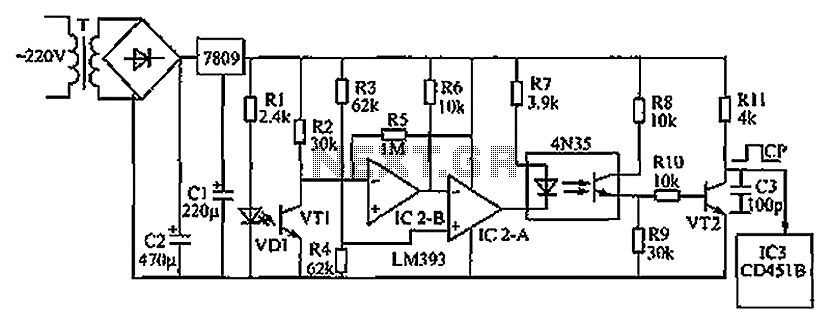
The circuit depicted in the figure operates as follows: when the phototransistor VT1 detects infrared light emitted by the infrared light-emitting diode, it enters a conductive state. This action causes the inverting input of comparator IC2-B, connected to pin...
For capacitor C3, a 100pF capacitor is placed across resistor R2. The circuit functions similarly to previous configurations, although no explanation is provided. The purpose of this component may be self-evident to experienced users, but it may not be...
This simple circuit is based on the well-known integrated circuit LM3915. The main characteristic of this integrated circuit is its ability to manage 10 Light Emitting Diodes (LEDs) in a logarithmic scale, with a 3dB difference between the LEDs,...

This design outlines a simple wideband output amplifier suitable for use as a 50-ohm transmission line driver. The circuit is constructed using the CA3140 operational amplifier. When utilized alongside the function generator and sine wave shaper circuits, it delivers...
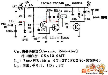
The quartz crystal oscillator circuit is highly advantageous in terms of frequency stability. Even the Voltage-Controlled Crystal Oscillator (VCXO) circuit, which allows for significant frequency changes, typically experiences only about a 1% variation. However, the linear range of control...
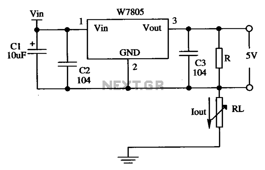
The circuit is composed of a W7805 positive current source application integration circuit that includes a voltage regulator. The W7805 regulator operates in suspension. A resistor is placed between its output terminal and the common terminal, forming a constant...