
Field-strength meter circuit

The detector-based meter operates on a straightforward principle where it measures the power levels of a transmitter by detecting the electromagnetic fields generated. Typically, such meters are designed with a simple diode detector, which rectifies the RF signal to provide a readable output on a calibrated scale. The sensitivity of this type of meter is generally limited, meaning it may not accurately reflect the true power levels, especially in more complex transmission scenarios.
The construction of a basic detector-based meter involves a few key components: an antenna for capturing the RF signal, a diode for rectification, a filter circuit to smooth the output, and a display mechanism, often an analog needle or digital readout. The antenna is usually tuned to the frequency of interest, allowing the meter to pick up the relevant signals effectively.
In practical applications, while such a meter can provide a quick assessment of transmitter power, its limitations should be acknowledged. Factors such as frequency response, dynamic range, and calibration accuracy can affect the readings. For more precise measurements, advanced equipment such as a true power meter or spectrum analyzer would be recommended, as they can offer greater sensitivity and accuracy across a broader range of frequencies and power levels.
Overall, while a detector-based meter serves as a useful tool for basic assessments, it is not suitable for applications requiring high precision or detailed analysis of transmitter performance.You can`t expect great performance from such a simple detector-based meter. Sensitivity is just adequate enough to get a basic idea of the power that your transmitter is capable of.. 🔗 External reference
Related Circuits
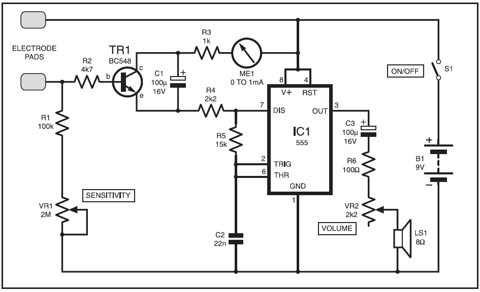
This instrument is designed to help relieve nervous tension for individuals returning home from work with lingering stress. Known as the Galvanic Skin Response Monitor, it operates based on changes in skin resistance that correlate with emotional states. Increased...
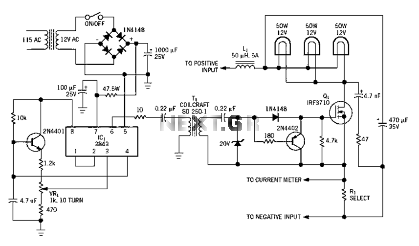
Electrical equipment provided for a power supply circuit design in the power section, as illustrated below. The power supply circuit design is a critical component in various electronic systems, serving as the backbone for powering other devices. The schematic typically...
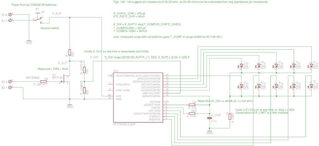
A method for measuring static electricity for a science project was sought. An old copy of "Getting Started in Electronics" by Forrest M. Mims III was referenced for guidance. To create a static electricity measurement circuit, a simple design can...

This circuit utilizes a 4049 integrated circuit (IC) to control a 2N2222 switching transistor. The transistor, in turn, drives a piezo transducer known as crystal 1. The circuit design begins with the 4049 IC, which is a hex inverter capable...
This circuit is a Digital Radar Speedometer that measures the speed of moving objects, particularly vehicles such as cars. The speed is displayed in kilometers per hour (KPH) and features a three-digit display. The radar operates using laser reflection...

This stereo balance indicator circuit diagram is designed using a few common external components. The schematic circuit is simple to build and provides a visual indication with LEDs for left, right, and center balance. Outputs from each channel are...