
Fixed-Current Regulator

The described circuit functions as a precise current source, essential for various electronic applications where stable current is required. The use of a transistor (Q1) allows for efficient current management, as the transistor's characteristics ensure minimal variation between collector and emitter currents. The operational amplifier plays a crucial role in maintaining the desired output by continuously adjusting its output to match the reference voltage set by the voltage divider formed by resistors R1 and R2.
In this configuration, the voltage divider outputs a stable 14 V, which is critical for the operation of the circuit. Resistor R3 serves as a reference input to the operational amplifier, ensuring that the output voltage remains stable despite variations in load or supply voltage. The feedback mechanism provided by the operational amplifier guarantees that the voltage at the junction of R4 and R5 remains constant, thereby stabilizing the current flowing through R5.
The choice of R5 is particularly important, as it directly influences the output current. By adjusting R5, the current can be precisely controlled; halving R5 will double the output current to 2 mA, demonstrating the flexibility of the circuit design. This feature is beneficial in applications requiring different current levels without the need for redesigning the entire circuit.
Overall, this fixed current source design is robust and adaptable, making it suitable for integration into larger electronic systems where consistent current delivery is paramount. Proper selection of components and careful consideration of circuit parameters will ensure optimal performance and reliability in practical applications. This fixed 1-mA current source delivers a fixed current to a load connected between Ql"s collector and ground; the load can be anywhere in the range from 0 to 14 . The circuit is powered from a regulated 15-V supply, and the R1/R2 voltage divider applies a 14-V reference to R3. The op amp"s output automatically adjusts to provide an identical voltage at the junction of R4 and R5.
That produces 1 V across R5, resulting in an R5 current of 1 mA. Because that current is derived from Ql"s emitter, and the emitter and collector currents of a transistor are almost identical, the circuit provides a fixed-current source. The output current can be doubled by halving the value of R5.
Related Circuits
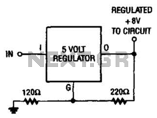
If locating an 8-V regulator proves difficult, a 5-V unit can serve as a replacement by connecting the regulator as illustrated here. In electronic circuits, voltage regulators are essential components that maintain a constant output voltage regardless of variations in...
There will be many times where it is desirable to use the P05 supply module from a higher voltage source. For example, if you want to add balanced inputs to a power amplifier, then you need a +/-15V supply,...
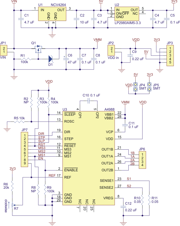
Best 1183 - A4988 Stepper Motor Driver Carrier with Voltage Regulator in Robot Italy. The A4988 stepper motor driver carrier with voltage regulators is a breakout board for Allegro's easy-to-use A4988 microstepping bipolar stepper motor driver. The board has...
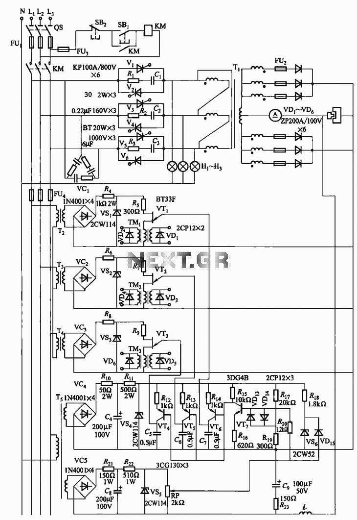
The 300A-18V three-phase thyristor power regulator circuit is designed for electrolysis applications. It can output a direct current of 3000A at an adjustable voltage of 18V, providing a power supply solution for various processing needs. The circuit comprises a...
The transformer has a 240V primary and has a secondary rated 24V at 2A. The bridge rectifier contains 4 diodes, their current rating needs to be high with respect to the transformers output current; if not the current may...
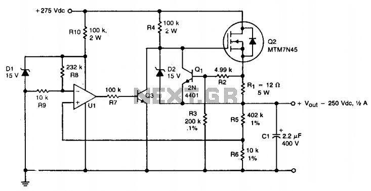
A TMOS MTM7N45 (Q2) is utilized as a series pass element in a linear high voltage supply that accepts +275 V unregulated and produces 250 V regulated with foldback current limiting. A 15 V zener diode (D1) provides the...