
Variable Power Supply Using Fixed Regulator
The described circuit consists of a transformer, a bridge rectifier, several capacitors, and an inductor, forming a basic power supply system. The transformer steps down the mains voltage of 240V to a lower, usable voltage of 24V AC on the secondary side, with a current rating of 2A. This transformer is crucial for providing the necessary voltage reduction for downstream applications.
The bridge rectifier, composed of four diodes arranged in a bridge configuration, converts the AC voltage from the transformer into pulsating DC. It is essential that the diodes used can handle the maximum output current of the transformer to prevent damage. The MR751 diodes, rated at 6A, are suitable for this application, and the 1N5400 diodes are also a viable alternative due to their robust current handling capabilities.
C1 serves as the main filtering capacitor, smoothing the rectified output to reduce voltage ripple. It is typically rated for a higher voltage than the peak output from the rectifier, ensuring reliability. The filtering process is further enhanced by the combination of inductor L1 and capacitor C3, which together form an LC filter. This configuration effectively reduces the ripple voltage, providing a more stable DC output.
C2 and C4 are decoupling capacitors strategically placed to further minimize any remaining ripple and noise in the power supply. These capacitors help maintain stable voltage levels for sensitive components connected to the power supply by filtering out high-frequency noise that could affect their operation.
Overall, this circuit exemplifies a fundamental approach to converting and smoothing AC voltage into a stable DC supply, suitable for various electronic applications. Proper selection of components, particularly the rectifier diodes and filtering capacitors, is crucial for ensuring the longevity and reliability of the circuit.The transformer has a 240V primary and has a secondary rated 24V at 2A. The bridge rectifier contains 4 diodes, their current rating needs to be high with respect to the transformers output current; if not the current may damage the diodes. I used MR751 which is rated 6 amps, but another good choice is 1N5400. C1 is the mainfiltering capacitor, the supply is further smoothed by the combination of L1 and C3. C2 and C4 are decoupling capacitors; their action further reduce ripple factor. 🔗 External reference
Related Circuits
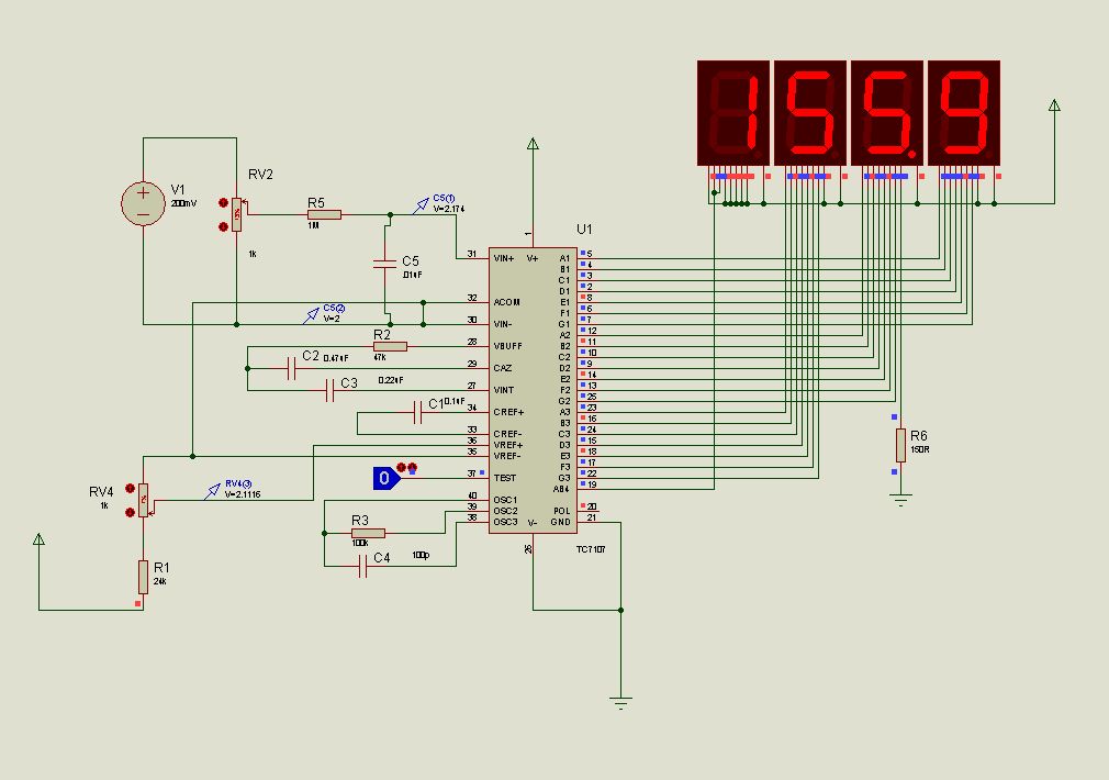
This document presents new models of a 3-digit common cathode (CC) and common anode (CA) multiplexed 3-digit voltmeter chip, specifically the TC7107 (ICL7107). It features a thumb switch with a common pin for BCD and hexadecimal outputs. The TC7107 is...
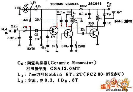
The quartz crystal oscillator circuit is highly advantageous in terms of frequency stability. Even the Voltage-Controlled Crystal Oscillator (VCXO) circuit, which allows for significant frequency changes, typically experiences only about a 1% variation. However, the linear range of control...
This motor driver delivers power from the capacitor to the motor when the capacitor is charged to 1.75V by the solar cell. After powering the motor, the capacitor. The motor driver circuit is designed to efficiently transfer energy stored in...
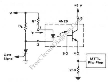
Interfacing high power loads can be accomplished in various ways, including the use of voltage divider resistors, transformers, or optocouplers. The circuit illustrated below employs the optocoupler method. This optocoupler facilitates logic level translation with flexible input, accommodating a...
A variable audio oscillator operates within a frequency range of 20 hertz to 20 kilohertz. The circuit utilizes an Intersil 8038 waveform generator, which is designed in a 14-pin dual in-line package (DIP). The variable audio oscillator circuit is designed...
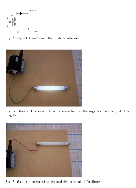
A high-voltage generator has been designed utilizing a flyback transformer as the output stage. The circuit diagram for the flyback transformer is illustrated in Figure 1. The high-voltage generator operates by converting low-voltage DC input into high-voltage AC output...