
300A-18V three-phase thyristor power regulator circuit for electrolysis
The 300A-18V three-phase thyristor power regulator circuit is a sophisticated electronic system tailored for high-current electrolysis processes. The design emphasizes efficiency and stability, utilizing thyristors to control the output voltage and current levels. The circuit architecture consists of several critical components: the main power circuit handles the high current, while the trigger circuit activates the thyristors at precise intervals to regulate the power delivered to the load.
The voltage negative feedback system is a crucial feature that enhances stability and performance. By sampling the output voltage from the rectifier, the feedback loop adjusts the operation of the thyristors to maintain the desired output voltage despite variations in load conditions. The use of a reactor L introduces a controlled inductance into the circuit, which helps smooth out fluctuations and provides a stable operating environment. The potentiometer RP allows for fine-tuning of the voltage output, enabling operators to adjust the system to meet specific processing requirements.
Components R23 and C9 form a differential feedback network that further stabilizes the output by responding to changes in load and voltage. This automatic voltage regulation ensures that the system can adapt to varying operational demands without manual intervention, significantly improving reliability.
The integration of a single-junction transistor relaxation oscillator is an innovative approach to generating the necessary trigger pulses for the thyristors. The narrow pulse width produced by this oscillator is essential for the accurate timing of the thyristor firing, which is critical for maintaining the desired output characteristics. The design also incorporates a transformer Ti that is responsible for distributing power across the three phases, effectively balancing the load and enhancing overall system performance.
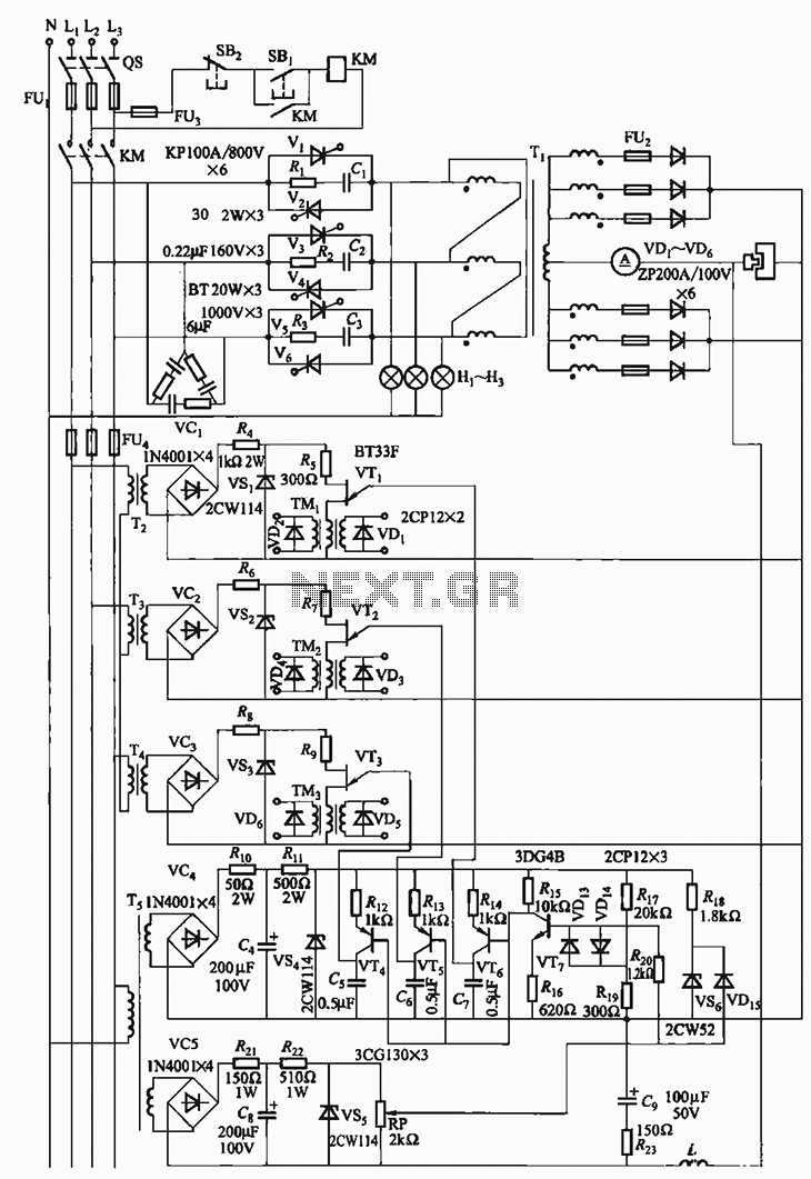
Finally, the inclusion of a 150W lamp load serves as a practical demonstration of the circuit's capabilities, allowing for real-time testing and validation of the system's performance under operational conditions. This comprehensive design ensures that the 300A-18V thyristor power regulator circuit is not only effective for electrolysis applications but also adaptable for various industrial power supply needs.300A-18V three-phase thyristor power regulator circuit electrolysis It can output DC 3000A, 18V (adjustable), power supply solution processing. Circuit from the main circuit, trigger circuit, part of the synchronous power, DC power, voltage negative feedback
circuit and protection circuit. Voltage negative feedback voltage is removed from the cell (ie, the rectifier output), the reactor L superimposed on a given voltage (by the potentiometer RP to the drawing). Voltage differential negative feedback by the R23 and C9. It plays the role of regulator with automatic voltage negative feedback. Since the single-junction transistor relaxation oscillator output pulse is narrow, in order to make reliable short pulse to trigger the transformer Ti of three phases in parallel a 150W lamp load.
Related Circuits
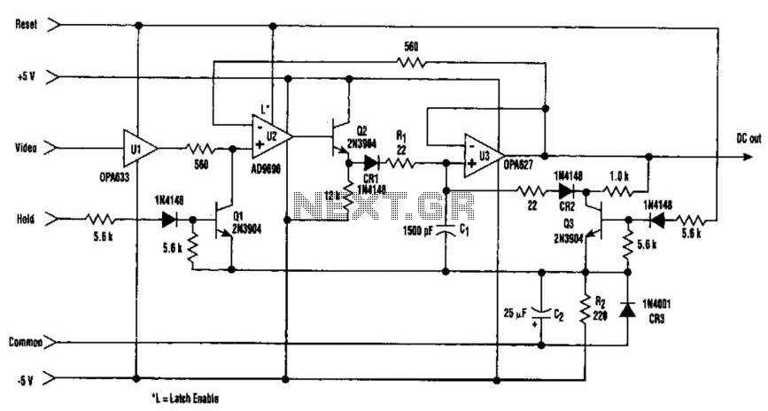
The amplitude of a video signal can be measured using a straightforward circuit that functions as a modified standard peak detector. This device is capable of verifying RGB signals produced by video RAMDACs. U1 is a high-speed buffer, while...
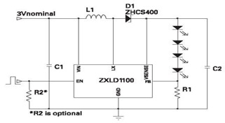
The ZXLD1100 is a PFM flyback DC to DC boost converter that operates in discontinuous mode. The following circuit diagram illustrates the configuration of four LED drivers for handset LCD backlighting using this device. The ZXLD1100 is designed to...
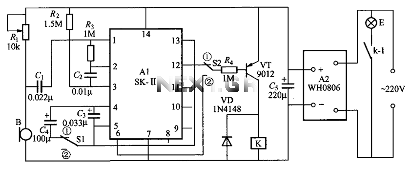
The circuit consists of an acoustic sensor, SK voice circuit, relay control circuit, vocal music circuit, and an AC buck rectifier circuit. The described circuit integrates several key components, each serving a distinct function to achieve the desired operational characteristics....
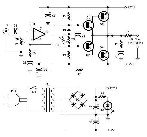
This is a circuit schematic diagram for a power amplifier utilizing the IC TLE2141C. The TLE2141C is a low-noise, high-voltage, high-slew-rate operational amplifier. It offers a frequency response from 30 Hz to 20 kHz with a variation of 1...
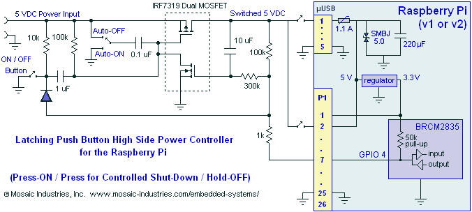
A momentary contact push button switch can be utilized to conveniently turn the Raspberry Pi (RPi) ON and OFF. Pressing the button will apply power to the micro USB header, maintaining power while the Raspberry Pi initializes and starts...

The power is all in the timed switching process. There are two main principles I use of switching the radiant energy the John Bedini way. First, the SG/SSG, Icehouse unidirectional circuit or John Bedini Monopole with the School Girl...