
Fixing Laptops Motherboard
The process of repairing a laptop motherboard after a polarity reversal requires a systematic approach to disassembly and fault diagnosis. The initial step involves referring to a service manual that outlines the disassembly process, typically consisting of numerous screws and connectors. Careful documentation is essential; labeling screws according to their removal order can significantly aid in reassembly.
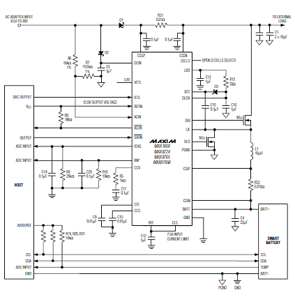
Once the motherboard is accessible, the next challenge is identifying the faulty components. In this case, the lack of comprehensive circuit diagrams in the service manual necessitated sourcing information from component datasheets available online. By focusing on the power supply subsystem, which includes critical components such as power supply controllers and battery charger ICs, it is possible to reconstruct the circuit diagram and identify potential faults.
Testing the motherboard under power is a critical step in fault diagnosis. Measuring voltages at various points can help pinpoint the location of the failure. In this instance, a broken diode was discovered, which was crucial for the operation of the battery charging controller. The identification of this component as faulty led to a practical solution: replacing the damaged diode with a compatible part.
The repair involved improvisation, such as using a 1N4148 diode with soldered extensions to fit the existing circuit layout. This approach highlights the importance of adaptability in electronics repair, as standard components may not always match the original specifications. Tools such as a small soldering iron, magnifying glass, and thin wire are essential for working with densely packed surface-mounted components.
Overall, the process emphasizes the value of resourcefulness, careful documentation, and a methodical approach to troubleshooting and repairing electronic devices.I managed to break my laptop, by reversing the polarity of a universal power supply. The repair shop diagnosed the problem as a failed motherboard, and asked for ‚¬659 to replace it. I found the price preposterous and the notion of throwing away a motherboard for a single failed component ecologically unsound. Here is how I fixed the laptop on my own, and what I learned in the process. Thankfully, I was quickly able to find a service manual. The trouble shooting guide quickly led me toward the same direction as that of the repair shop: "Replace the motherboard". However, the manual also provided me the exact 28-step sequence for extracting the motherboard. It involved removing more than 40 screws, unseating about a dozen connectors, and separating a similar number of parts.
Lesson 2 Keep notes on which screw belongs to which part. Place screws on paper sheets numbered by the step on which you removed them. This will help you reassembling the chaos into one working piece. Lesson 3 Release connectors before pulling flat cables. Usually you pull a retaining part out or up. Be careful, flat cables and their connectors are very fragile. Locating the problem on the motherboard proved a lot more difficult. When I was young I remember consumer electronics, like tape recorders, coming with their circuit diagram as part of their documentation. I was fascinated by them. Later those diagrams got relegated to service manuals. The technical reference manual of the original IBM PC contained the detailed circuit diagram of every part.
Sadly, all my laptop`s service manual offered was a, useless for my purposes, block diagram. This last strategy proved easy to follow, once I located the key components used for the power supply subsystem: a power supply controller and a battery charger IC made by Maxim. The corresponding data sheets gave me a circuit diagram that was very close to that I saw on the motherboard.
Lesson 6 You can reverse engineer complex systems by reading the application notes of key components used; original equipment manufacturers seem to follow closely the plans of component suppliers. Locating the data sheet for each component on the internet proved invaluable. I thus quickly found out that tens of what looked like eight-pin ICs were in fact MOSFETs packaged with a Schottky diode.
Given that the motherboard was in theory a complete write-off, I decided to test it under power. By measuring voltage at various points, I found that a diode that was supposed to supply the battery charging controller, was broken. When I short-circuited the diode and found voltage at various other motherboard locations that were previously dead, I was sure I had located the culprit.
Lesson 8 To locate a fault be prepared to work top-down (from subsystems to components), or bottom-up (look for a faulty component), or to start from the fault`s reason (e. g. reversed polarity), or its symptom (e. g. lack of power). Fixing the problem on a dense board of surface-mounted components wasn`t however trivial. Fortunately, finding a replacement part was easy. According to the application note I could use a simple signal diode, so I just pulled a 1N4148 diode out of my component drawer.
To fit it on the circuit board, I soldered thin insulated solid copper wire at its two ends, and placed the package in a heat-shrink tube. This allowed me to place the package nearby, and solder the two ends on the pads left by removing the original diode that had failed.
Lesson 9 For the fix you`ll have to improvise and make concessions. The tools of your trade are a very small soldering iron, a magnifying glass, thin wire-wrap cable, and insulation materials. 🔗 External reference
Related Circuits
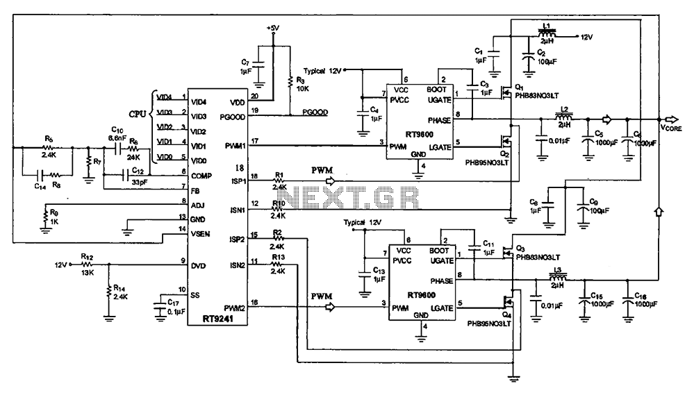
A typical computer motherboard CPU power supply circuit is primarily composed of the main power supply management chip RT9241 and additional components from the power management chip RT9600. The voltage command signal from the CPU is input into the...
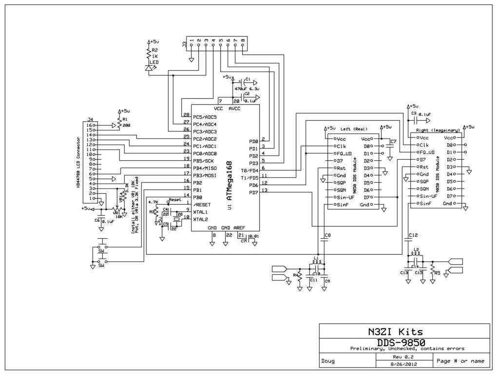
This project supports an LCD module (16x2 HD44780) and includes an AVR Micro ATMEGA168 programmed with demo/test code. It features a high-quality PCB made in the USA, which includes solder mask, plated through holes, and is RoHS compliant. The...
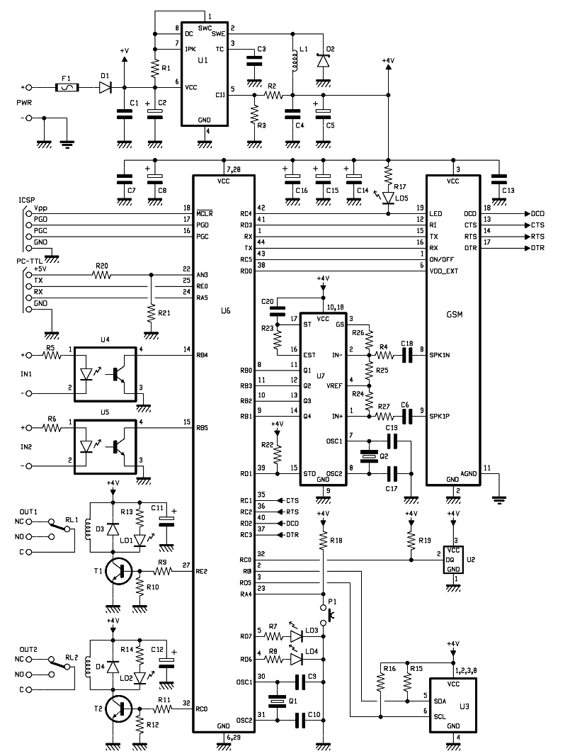
The entire remote control is managed by a PIC that oversees the GSM/GPRS module's operations, monitors room temperature via a Dallas DS1820 smart probe, controls the logical state of two opto-isolated inputs, and sends commands to two relays. Additionally,...
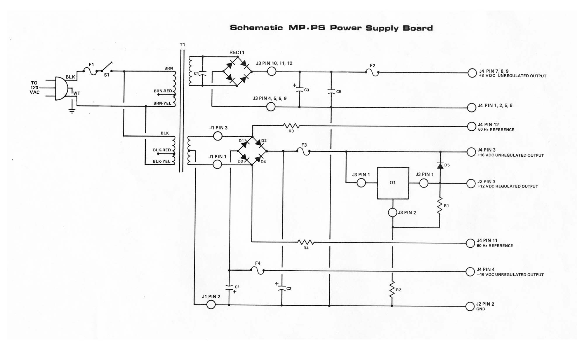
The MP-P2 Power Supply is engineered to provide power to the motherboard and its associated plug-on boards, including the MP-09 Microprocessor Board, disk controller board, memory boards, and up to eight interface boards within the SWTPC Computer system. It...