
AD9850 DDS Module Motherboard
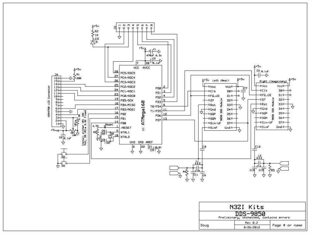
This electronic schematic is designed for a versatile microcontroller-based frequency generator that integrates an HD44780-compatible LCD for user interaction and display. The core of the system is the Atmel AVR ATMEGA168 microcontroller, which serves as the brain of the circuit. The microcontroller is preloaded with demo code that facilitates the initialization and operation of two Direct Digital Synthesis (DDS) modules, specifically the AD9850 or AD9851 types. These modules are capable of generating precise waveforms, including sine and square waves, across a frequency range extending from 0Hz up to 40MHz, with potential expansion to 50MHz through additional filtering.
The PCB is designed with careful consideration for quality and compliance, featuring solder mask and plated through holes, ensuring durability and ease of assembly. The layout accommodates a 40-pin female header socket, which can be segmented into smaller headers to interface with the DDS modules and the LCD. The inclusion of multiple capacitors, such as electrolytic and bypass capacitors, contributes to the stability and performance of the power supply, which is specified to be 5VDC with a tolerance of ±0.2V.
The output specifications of the circuit indicate that it can produce two sine wave outputs at approximately 1V peak-to-peak at 7MHz under no load conditions, alongside two square wave outputs at approximately 5V peak-to-peak. The system's design allows for a step size as low as 0.03Hz, enabling fine adjustments to the output frequency.
User interaction is facilitated through push buttons that allow for incremental adjustments to the DDS output frequencies, with real-time feedback provided on the LCD display. The LCD is configured to operate in 4-bit mode, displaying frequency values and phase information in hexadecimal format. This comprehensive setup not only serves as an educational tool for users interested in electronics and radio frequency applications but also provides a robust platform for experimentation and further development in signal generation technology.Supports LCD Module (16x2 HD44780) Includes AVR Micro ATMEGA168 programmed with demo/test code. Top Quality US made PCB (w/Solder mask, Plated through holes, RoHS compliant) Designed by a long term amateur radio operator(N3ZI) and engineer (BSEE) Experimenters Kit Parts include: PCB, top quality US made Atmega168 micro programmed with demo code Socket for micro 40Pin female header which and be cut to make 2 10 pin headers (for 1 DDs Module) and a 16 pin header (for LCD) C1, Electrolytic cap C2, C3, C6, 0. 1uF bypass caps. VR1- 3. 3K fixed for LCD Bias R1 200ohm for LCD backlight. R3 4. 7K for reset line 2 Switches. Specifications Power requirements: 5VDC, regulated, filtered, and stable +/-. 2V Current 20mA, Control board plus LCD DDS Modules, 100 to 170mA each. Recommended supply capability, 500mA Outputs 2 Sine wave, approx 1v p-p @7MHz, no load. 2 Square wave, approx 5v p-p @ 7MHz. Frequency range 0Hz to 40MHz. Expandable to 50MHz with additional filter (provision on PCB) Step Size, as low as 0. 03Hz. DDS Type AD9850 or 9851 PCB Size 3. 15 in x 2. 00 inch Thickness, 1. 75 inch, including DDS Modules, LCD LCD Type, HD44780 compatible, 16 Characters, 2 lines, with 16 pin single row connector, and 5mA backlight.
(LCD Not included with this kit, but these types of LCD are readily available on for ~$4. ) Microprocessor type, Atmel AVR ATMEGA168 programmed with Demo code. Demo Code functions Initialization of 2 DDS Modules Initialization of LCD modules (in 4 bit mode) Set frequencies in DDS modules to 7. 076MHz and 7. 106MHz Push buttons will increment and decrement those frequencies. LCD will display frequency and phase words (in hex) sent to each DDS module 🔗 External reference
Related Circuits
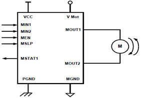
The schematic presented illustrates a 5A H-Bridge Module designed for the operation of a single Bipolar DC motor. The H-Bridge Module includes a header set (J2) and a connector terminal set (J1). Below is the pinout description for the...

This circuit is a Phase-Locked Loop (PLL) system designed for use as an FM demodulator. The output of the Voltage-Controlled Oscillator (VCO) follows the FM signal, with the input voltage to the VCO being proportional to its output frequency....
The CAMD CM8870 CM8870C offers complete DTMF receiver functionality by combining both the band-split filter and digital decoder capabilities into a single 18-pin DIP, SOIC, or 20-pin PLCC package. The CM8870C is produced using advanced CMOS process technology, ensuring...

A notable observation is that connecting both the circuit ground and the antenna to separate ground points significantly enhances power output compared to using a standard antenna and coil setup. A coil similar to one described on an ambient...
SEL2411AA is a sub-package of SEL2410. For a detailed description, please refer to SEL2410. The datasheet for SEL2411AA can be downloaded from the link provided below. By Pericom Semiconductor Corporation. The SEL2411AA is a specialized electronic component that serves as...
The laptop was damaged due to reversing the polarity of a universal power supply. A repair shop diagnosed a failed motherboard and quoted a replacement cost of €659, which was deemed excessive and ecologically unsound. The individual opted to...