
Flagpole light with burned out bulb sensor
An automatic garage door opener system has been integrated with a flagpole illumination monitoring circuit for enhanced convenience and security. The system utilizes an X-10 light switch module to automate the flagpole light, which is powered by a transformer that converts 110V AC to 12V DC. This light is required to remain illuminated at night to adhere to flag protocol. The initial installation was subject to vandalism, prompting the replacement of the light with a more robust floodlight that is strategically mounted on the garage roof.
To ensure the flag remains illuminated, a dual-color LED indicator system was developed. This system provides real-time feedback on the operational status of the flagpole light: a green LED indicates that the light is functional and the flag is illuminated, while a red LED signals a burned-out bulb condition. Additionally, a large green LED is used to indicate the status of the garage door, providing a comprehensive overview of both systems at a glance.
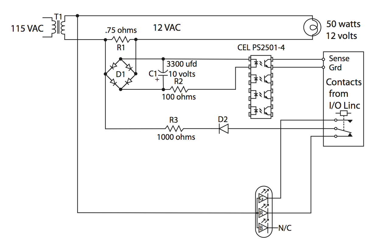
The monitoring system employs a current-sensing mechanism to detect the operational state of the floodlight. Specifically, the Insteon I/O Module is utilized to integrate the flagpole light's status with a home automation system. This module features a form C relay that allows for remote monitoring and control. The relay's contacts can be activated via power line signals or by applying a voltage to the sense contacts.
An opto-isolator is incorporated to facilitate the current monitoring process. It consists of an internal LED that activates a phototransistor, effectively grounding the sense terminal when the floodlight is operational. The current flowing through the floodlight is measured using a 0.75-ohm shunt resistor, which generates a voltage drop proportional to the current flow. With a 50-watt floodlight operating at 12 volts, a current of approximately 4 amps is expected, leading to a 3-volt drop across the shunt resistor. This voltage drop is used to power the opto-isolator, ensuring accurate monitoring of the floodlight's operational state and providing timely alerts for maintenance or replacement needs.
Overall, this comprehensive system enhances the functionality of both the garage door and flagpole illumination, integrating advanced monitoring capabilities with user-friendly indicators for efficient management.I was offered an automatic garage door opener, a seeded back lawn, a fireplace and a refrigerator. I suggested that I had always wanted a flagpole so the developer told me that they could add a flagpole. Therefore I have the only 25 foot commercial flagpole in the development. Some of my neighbors refer to me as the Flagpole Guy. I`m not always home at sunrise and sunset so instead of raising and lowering my flag daily I have it illuminated at night as required by protocol. The light the developer installed was installed in the ground with the switch inside the front door. I automated the light with a X-10 light switch module to go on at sunset and off at sunrise daily. This turns on the 110 volt to 12 volt transformer that powers the light. The light the developer installed in front of the pole was damaged several times by vandals. Here in Arizona many of us have desert landscaping in the front with stones and rocks. They would use the rocks to break the glass and the bulb. This year I bought a new light system that mounts on the corner of the garage roof. It`s a 12 volt, 50 watt quartz-iodine bulb floodlight. Within two weeks of installing it the bulb burned out. I didn`t know how long my flag was un-illuminated and that embarrassed me. So I decided to build a monitoring system with an indicator LED inside, to tell me if the light was powered and if the bulb was burning.
I used a dual color red and green LED where green meant the light was powered and the flag was illuminated and the red LED to tell me the light was powered but the bulb was burned out. Next to the inside door to the garage I have a control to open and close the garage door. I have a large green LED mounted on it to tell me if the garage door is open or closed. I decided to mount the flagpole sensor on the same housing. I glance at it when I go to bed and two green LEDs mean the garage door is closed and the flagpole is lighted.
To just tell if the flagpole light was turned on would be simple enough. Just rectify the AC from the 12 volt transformer powering the light and light a green LED. The flaw is that it won`t tell me if the bulb has burned out. I needed a circuit that monitored the current going to the bulb. Burned out bulb, open circuit, no current flow. Insteon makes a nice module for Home Automation called the I/O Module. The module integrates the burned out bulb sensor with my home automation system. It makes the status of the flagpole light available on the home automation system where I can use it to to control other devices if I want. For instance I could make a failure of the bulb cause the home automation system to flash a house light.
For now I`m content with it operating a LED. The module contains a form C contact, that consists of a common lead with a normally closed contact and a normally open contact. The contacts can be operated in either of two ways. You can address the module through the power line of the house and remotely turn it on or off or you can apply either a ground or 5 volts to the sense contacts on the module to switch the form C contact.
I decided to effectively apply a ground to the sensing input by way of an opto-isolator. The opto-isolator has an internal LED which shines on a photo transistor. The light turns the transistor on and that transistor effectively shorts the sense terminal to ground. The voltage to energize the opto-isolator LED is derived from the. 75 ohm shunt in series with the floodlight illuminating the flag. A 50 watt bulb powered by 12 volts creates a 4 amp current flow. I put a. 75 ohm resistor in series with the floodlamp and this would generate a 3 volt drop across the. 75 ohm resistor. The power dissipated by the. 75 ohm re 🔗 External reference
Related Circuits

The described circuit counts the number of interruptions of an infrared beam. This could be used to tally the number of people entering a room or to monitor how often an object, such as a ball, passes through an...

The current application involves the use of the VHDL hardware description language for designing a traffic light system controller circuit. This design is implemented within the Altera MAX PLUS EDA software environment, which facilitates compilation, simulation, and programming for...
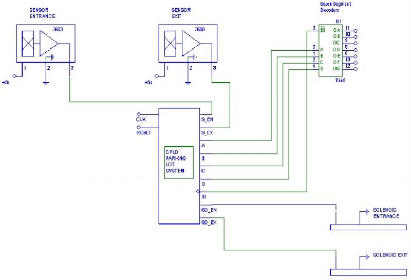
The objective of this project was to create a parking lot management system. The project was divided into five design phases. Throughout the development process, various challenges were encountered, and progress was made compared to the reports from the...
The following circuit illustrates a simple light sensor circuit diagram. Features include crocodile technology for simulating circuit operation, and an LDR (Light Dependent Resistor) is utilized. The simple light sensor circuit operates on the principle of light intensity detection using...

This circuit is an IC-controlled emergency light system. It automatically switches on the light during a mains failure and includes a battery charger with overcharge protection. When the mains power is absent, relay RL2 is in a de-energized state,...

The circuit utilizes a 555 integrated circuit (IC) functioning as an astable multivibrator. When a positive 9 volts is applied to pin 8, the circuit generates sound through a speaker. The connection to pin 8 is routed through a...