
neon emergency light battery schematic

This circuit design integrates several essential components to ensure reliable operation during power outages. The use of the NE555 timer IC in astable mode is crucial for generating a stable pulse signal, which is necessary for driving the MOSFETs effectively. The push-pull configuration of the MOSFETs allows for efficient power amplification, facilitating the driving of a fluorescent tube with minimal energy loss.
The relay RL2 plays a pivotal role in switching the power source from the mains to the battery when a power failure occurs. Its de-energized state ensures that the battery supply is routed to the inverter section, allowing for seamless transition and uninterrupted lighting. The inclusion of switch S1 provides user control over the lighting, enabling the option to turn off the light during an outage if desired.
The overcharge protection circuit, implemented with the LM308 operational amplifier, is a critical safety feature. By maintaining a reference voltage of 6.9 volts, it effectively monitors the battery voltage and prevents overcharging, thereby extending the lifespan of the battery. Diodes D5 and D6 work in tandem to establish this reference voltage, ensuring that the charging process remains within safe limits.
Overall, this emergency light circuit combines functionality, efficiency, and safety, making it a reliable solution for lighting needs during power interruptions. The careful selection of components and their configuration ensures that the system operates smoothly and effectively in various scenarios.This circuit is IC controlled emergency light. This series of automatic switching-on of the light on mains failure and battery charger with overcharge protection. When mains is absent, the relay RL2 is in deenergised state, feeding battery supply to the inverter section via its N / C contacts and switch S1.
The inverter section comprises IC2 (NE55 5) which is used in a stable fashion to produce sharp pulses at the rate of 50 Hz for driving the MOSFETs. The output of IC3 is fed to the gate of MOSFET (T4) directly while it is applied to MOSFET (T3) after inversion by gate transistor T2.
Thus the power amplifier built around MOSFETs T3 and T4 functions in push-pull mode. The output across the secondary of transformer X2 can easily drive a 230-volt, 20-watt fluorescent tube. In case light is not required to be on during mains failure, simply flip the switch S1 to off position.
Battery overcharge preventer circuit is built around IC1 (LM308). Its non-inverting pin is held at a reference voltage of approximately 6. 9 volts which is obtained using diode D5 (1N4148) and 6. 2-volt zener D6. 🔗 External reference
Related Circuits
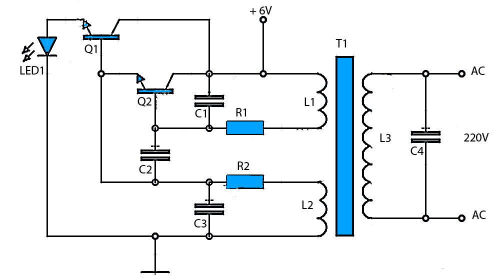
6V to 220V Inverter Schematic. Starting from a 6-Volt input on the DC current to produce a 220-Volt AC output. The inverter circuit converts a low voltage DC input, specifically 6 volts, into a high voltage AC output of 220...
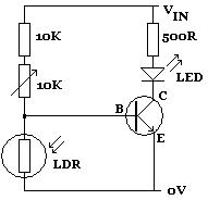
A Light Dependent Resistor (LDR), also known as a photoconductor, photoresistor, or photocell, is a commonly used electronic component that exhibits a decrease in resistance as the intensity of light striking its surface increases, and vice versa. Typically, LDRs...
The JarLight is a compact flashlight utilizing a white light-emitting diode (LED) and powered by a single battery cell. This configuration allows for a highly compact design with significant light output and extended operational life, both for the battery...
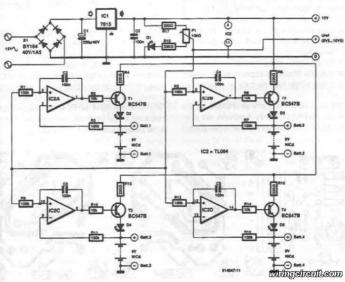
This electronic circuit diagram facilitates the design of a straightforward charging circuit for NiCd batteries. The charger is capable of simultaneously charging four 9V NiCd batteries, with the voltage being adjustable via a potentiometer labeled P1. The described circuit operates...
Simple pathway lighting that provides illumination for the path at night. Extension for the solar garden light. The toroid is bifilar wound. The described circuit involves a solar-powered pathway lighting system designed to illuminate walkways during nighttime. This system...
This circuit utilizes the widely available LM3914 integrated circuit (IC), which is straightforward to operate and does not require external voltage regulators due to its built-in voltage regulator. It can be powered from various sources. When the test button...