
Water Activated Sensor Alarm Using 555 PCB

The described circuit operates as a water detection alarm system, leveraging the 555 timer's astable multivibrator configuration to generate an audible alert when moisture is detected. The 555 timer is a versatile component frequently used in timer, delay, pulse generation, and oscillator applications. In this specific design, it is configured to oscillate continuously, producing a square wave output at pin 3.
The circuit's functionality hinges on the behavior of the NPN transistor in response to changes in resistance caused by water. Under normal conditions, the base of the transistor is not biased, keeping it in the off state. Once water bridges the contacts, the resistance drops, allowing current to flow into the base of the transistor. This action turns the transistor on, enabling current to flow from the collector to the emitter, thus powering the speaker and generating sound.
The choice of a 100 µF electrolytic capacitor in series with the loudspeaker serves to block any DC component from the output while allowing the AC signal (the audio tone) to pass through. This configuration protects the speaker from potential damage due to DC voltage. The resistors R1 and R2 are critical for setting the operating point of the 555 timer, ensuring it functions correctly within its desired frequency range. The values of these resistors can be adjusted to change the frequency of oscillation, which in turn affects the pitch of the sound produced.
Capacitor C1 plays a significant role in determining the frequency of the output signal. By varying its capacitance, one can tune the circuit to produce different tones, allowing for customization of the alarm sound. This feature can be particularly useful in applications where distinct alerts are required for different types of detection.
Overall, this circuit provides a practical solution for water detection, combining simple components to create an effective alarm system that can be easily adapted for various applications.The circuit comprises a 555 IC as the core. This is designed to work as an astable multivibrator. When we connect a positive 9 volt to pin no. 8, the circuit will produce a sound through speaker. But here the connection to pin 8 goes through the transistor BC 109c or BC 548. In this condition, the base of the NPN transistor haven`t any positive vo ltage. But when the resistance between the "contacts" is lower due to water, the transistor get it base voltage and the circuit will produce a sound. We can connect the the 555 output pin no. 3 to loudspeaker through a 100uF electrolytic capacitor. The resistors, R1 and R2 are used for IC biasing. We can change the tone of the sound coming from the speaker by changing the value of capacitor C1. 🔗 External reference
Related Circuits
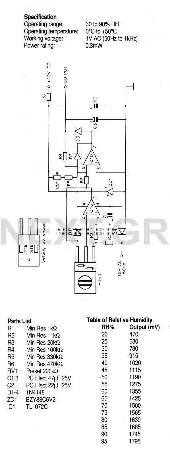
A humidity sensor with temperature compensation built-in. Never apply a DC voltage to the sensor, even measuring the sensor with an ohmmeter will damage the device, always ensure that an AC voltage is applied. Avoid condensation, freezing, dust, mist,...
NEC's UPB1008K is a Silicon RFIC specifically designed for handheld low-power, low-cost GPS receivers. The integrated circuit combines a low-noise amplifier (LNA) followed by a double-conversion RF/IF downconverter block and a phase-locked loop (PLL) frequency synthesizer on a single...

This device listens to conversations and then interjects words and phrases at inappropriate times. I got this box at a local thrift store for $1.50. It has a nice hinged top and a place to insert a panel with...
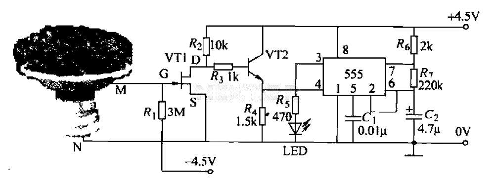
The flowers in pots require watering, as relying solely on the observation of moist soil surfaces can be unreliable. To address this issue, a flower watering indicator has been developed. This circuit includes a field effect transistor (VT1), a...
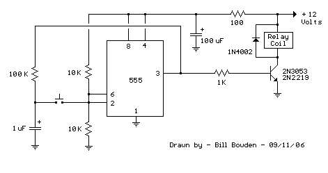
This 555 timer circuit below toggles a relay when a button is pressed. Pins 2 and 6, the threshold and trigger inputs, are held at 1/2 the supply voltage by the two 10K resistors. When the output is high,...
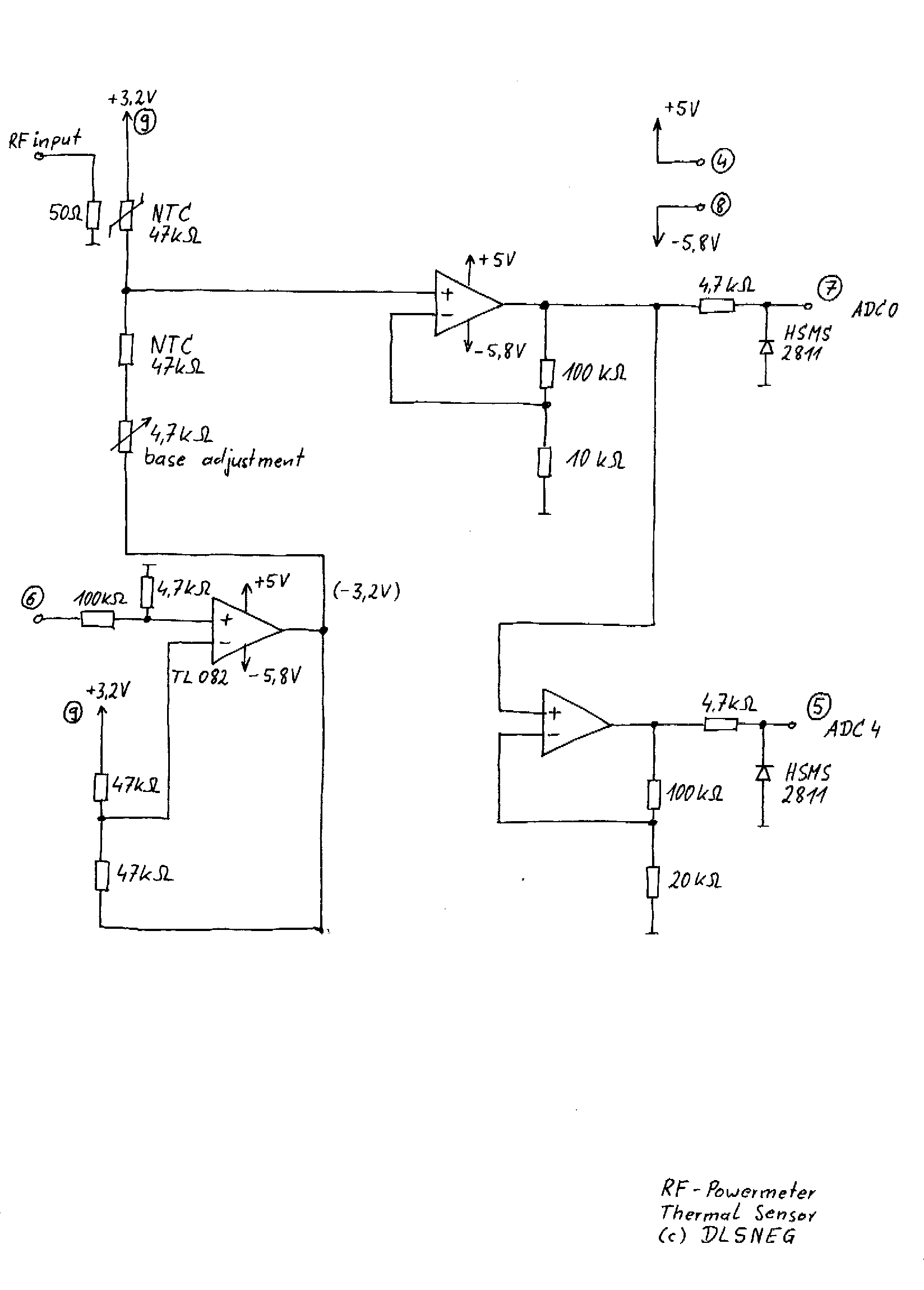
A few years ago, a diode-sensor based RF power meter was built using a 68HC11 microprocessor. Prior to that, an analog RF power meter with a thermal power sensor was developed. The datasheets for logarithmic amplifiers, which promised a...