Flasher with Beeper with description
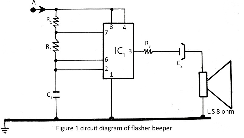
A flasher with a beeper is very easy to build and assemble. The flasher with a beeper is constructed using very common components, with various projects utilizing the NE555 timer IC.
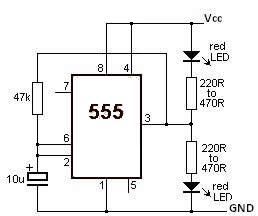
The flasher circuit typically employs the NE555 timer IC in astable mode, which allows it to generate a square wave output. In this configuration, the timer alternates between a high and low state, creating a flashing effect. The frequency of the flashing can be adjusted by selecting appropriate resistor and capacitor values connected to the timer's pins.
Incorporating a beeper into the circuit adds an auditory signal that coincides with the visual flashing. The beeper can be a simple piezoelectric element that is activated by the output of the NE555 timer. When the timer output goes high, it supplies voltage to the beeper, producing a sound that corresponds with the flashing light.
The basic components required for this project include the NE555 timer IC, resistors, capacitors, a power supply (typically 5V to 15V), a light-emitting diode (LED) for visual indication, and a piezoelectric beeper. The circuit can be assembled on a breadboard or PCB for testing and final implementation.
To enhance the functionality, additional features such as adjustable flashing rates or varying sound patterns can be integrated by modifying the component values or adding more circuitry. This simple yet effective design serves as an excellent introductory project for those learning about timer circuits and basic electronics.flasher with beeper in this site is very easy to build and assemble. flasher with beeper is build with very common components. various project using NE555 timer IC. 🔗 External reference
