
one transistor led flasher
The one-transistor LED flasher circuit operates by using the 2N3904 NPN transistor as a switching device. The self-flashing LED (LED 2) provides a pulsing signal to the base of the transistor, which controls the on and off states of the super bright LED. When LED 2 flashes, it generates a voltage at the base of the transistor, turning it on and allowing current to flow from the collector to the emitter, thereby illuminating the super bright LED.
The flash rate of the circuit is primarily determined by the 1k resistor, which is connected in series with the base of the transistor. Adjusting this resistor alters the charging and discharging time of the base-emitter junction, effectively changing the frequency of the flashes produced. A lower resistance value will increase the flash rate, while a higher value will decrease it.
In addition to the 2N3904 transistor and the 1k resistor, the circuit may include a few passive components such as a capacitor to stabilize the voltage and ensure consistent flashing. The super bright LED is connected in series with a current-limiting resistor to prevent excessive current from damaging the LED.
This simple yet effective circuit can be used in various applications, including decorative lighting, indicators, or as a basic teaching tool for understanding transistor operation in flashing circuits. Proper attention should be given to the power ratings of the components to ensure reliable operation.Here is a one transistor LED flasher circuit which will flash a super bright LED. The circuit is using single transistor as driver which is taking flash rate from the LED 2 which is a self flashing LED. The flash rate can be adjusted by changing the value of 1k resistor used in the circuit. The circuit is using 2N3904 🔗 External reference
Related Circuits
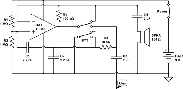
The circuit operates in receive mode, with the Push-To-Talk (PTT) switch enabling transmit mode. The speaker functions as both a microphone and a speaker. Most systems observed utilize a rocking armature transducer for the speaker. There is no base...
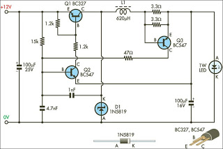
This circuit is designed to drive 1W LEDs that are commonly available. Their non-linear voltage-to-current relationship and variation in forward voltage with temperature necessitate the use of a 350mA constant-current power source as provided by this supply. The circuit...
This circuit, designed on request, has proven to be useful to indicate when the voltage in a power supply line is changing from 120V to 240Vac. It can be used in different circumstances and circuits, mainly when an increase...
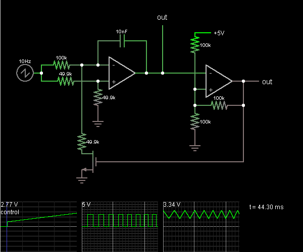
This circuit is a voltage-controlled oscillator, which is an oscillator whose frequency is determined by a control voltage. A 10 Hz sawtooth oscillator provides the control voltage in this case; this causes the frequency to rise slowly until it...

This circuit is for a temperature controlled constant current battery charger. It works with NICD, NIMH, and other rechargeable cells. The circuit works on the principle that most rechargeable batteries show an increase in temperature when the cells become...

Microdot - wrist watch LED pattern timepiece. This project is a circuit board designed for creating a wristwatch-sized version. The Microdot wristwatch project involves the design and implementation of a compact circuit board that integrates LED technology to display time...
Warning: include(partials/cookie-banner.php): Failed to open stream: Permission denied in /var/www/html/nextgr/view-circuit.php on line 713
Warning: include(): Failed opening 'partials/cookie-banner.php' for inclusion (include_path='.:/usr/share/php') in /var/www/html/nextgr/view-circuit.php on line 713