
FlasherCircuit using NE 555 IC for Lamp
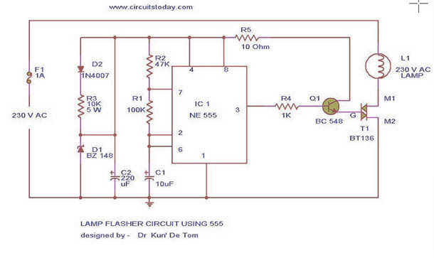
The lamp flasher circuit utilizes a standard NE555 timer IC, which is a versatile component widely employed in timing applications. In this configuration, the NE555 operates in astable mode, meaning it continuously oscillates between its high and low states, producing a square wave output. The frequency of this oscillation, and therefore the flashing rate of the lamp, can be adjusted by changing the resistance values of R2 and R3, as well as the capacitance of the timing capacitor connected to the discharge pin.
Diodes D1 and D2 serve a crucial role in providing a stable power supply to the NE555 IC. They rectify the AC mains voltage, ensuring that the IC receives a consistent DC voltage necessary for proper operation. The half-wave rectification allows only one half of the AC waveform to pass through, which is then smoothed out by a filtering capacitor (not explicitly mentioned but typically included in such designs) to provide a more stable voltage.
Transistor T1 acts as a switch that controls the flow of current to the triac, BT136. When the NE555 produces a high output, T1 is activated, allowing current to flow through the gate of the triac. The triac, once triggered, allows current to pass through the load (the lamp), enabling it to flash. Resistor R4 is essential as it limits the base current to Q1 (the transistor), protecting it from excessive current that could lead to damage.
Overall, this circuit effectively demonstrates the principles of timing, rectification, and control using common electronic components, making it suitable for various lighting applications where flashing effects are desired. The design is versatile, allowing for adjustments to the flashing rate, making it adaptable for different lamp types and user preferences.This is the circuit diagram of lamp flasher operated from mains. By this you can flash up to 200 Watt lamps at rates determined by you. IC NE555 is wired as an astable multivibrator for producing the pulses for flashing the lamp. The flashing rate can be set by the value of resistors R2 & R3. Diodes D1 & D2 provides a half wave rectified regulated supply for the IC. Transistor T1 is used to drive triac and triac BT136 for driving the load. Resistor R4 limits the base current of Q1. 🔗 External reference
Related Circuits
A 40-watt fluorescent tube lamp or two 20-watt tubes in series will be driven by this circuit. The transformer is wound on a ferrite rod with a diameter of 10 mm and a length of 8 cm. The circuit described...
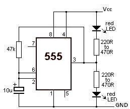
This LED flasher circuit utilizes the 555 timer integrated circuit (IC). The circuit diagram is straightforward and requires only a few external components. When operational, the red LEDs will flash sequentially at a predetermined frequency, similar to the indicators...
This circuit functions as a camera switch, allowing multiple cameras to be connected to a single monitor. It can operate in both manual and automatic modes. In automatic mode, the circuit utilizes a 555 astable multivibrator to generate a...

The circuit operates using binary signal statuses of "1" and "0". It also incorporates a frequency generator. The circuit described utilizes a binary signaling system, which is fundamental in digital electronics. The binary states "1" and "0" represent the two...
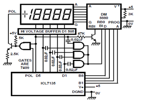
A circuit diagram for driving a plasma-type display using the ICL7135 is presented in the schematic. This application highlights the versatility of this integrated Analog to Digital Converter device. The ICL7135 is a high-precision, low-power, integrating Analog to Digital Converter...
This metal detector utilizes the CS209A integrated circuit manufactured by Cherry Semiconductor. The CS209A is a bipolar monolithic IC designed for metal detection and proximity sensing applications. It features two on-chip current regulators, an oscillator, low-level feedback circuits, a...