
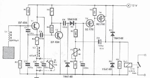
metal detector using cs209a
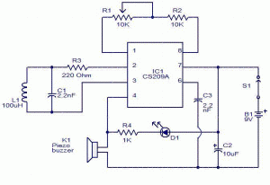
The CS209A metal detector circuit operates by leveraging the principles of inductive sensing. The oscillator generates a high-frequency signal that is influenced by the inductance of the coil, which is sensitive to the presence of metal objects. The LC tank circuit, consisting of an inductor (100 µH) and a capacitor, resonates at a specific frequency. When a metal object approaches the coil, the inductance increases or decreases, causing a shift in the resonant frequency of the LC circuit. This frequency shift is detected by the demodulation circuit, which extracts the relevant signal from the oscillator output.
The demodulator's role is critical; it processes the oscillator output to identify changes in amplitude, which correspond to the presence of metallic objects. The comparator then compares the processed signal against a predetermined reference level. If the demodulated signal exceeds this reference, the comparator triggers the complementary output stages, activating the LED and buzzer, thereby providing immediate visual and audible feedback to the user.
The design also includes an adjustable resistor (R5), which allows for calibration of the detector's sensitivity. During installation, it is essential to set R5 while ensuring that the LC circuit is free from interference by metal objects. This initial setup ensures that the circuit operates correctly and minimizes false positives.
Overall, the CS209A metal detector is an effective solution for various applications, including security, treasure hunting, and industrial metal detection. Its compact design and integrated features make it suitable for portable devices, while the simple installation process allows for quick deployment in various environments.This metal detector using CS209A made by Cherry Semiconductor. The CS209A is a bipolar monolithic integrated circuit for use in metal detection / proximity sensing applications. The CS209A metal detector IC has two on-chip regulators current, the oscillator and low-level feedback circuits, peak detection / demodulation circuit, a comparator and two
complementary stages. The oscillator output, along with an external LC network provides controlled oscillations, where the amplitude is highly dependent the Q of the LC tank. The demodulator senses the negative peak of the oscillator wrap and provides a demodulated waveform as input to the comparator.
The comparator sets the state of the complementary outputs by comparing the input of the demodulator to an internal reference. The detector is a single coil 100uH. The IC has an oscillator integral part of the strangulation of an external LC circuit is the inductance that is changed by the proximity of metal objects.
Is the change in the oscillation that is amplified and demodulated. LED 1 will light and the buzzer will sound when the inductance has changed. Installation is easy: R5 is adjusted with the LC away from any source of metal for the LED lights and buzzer. The control is reversed so that the LED turns off and stops ringing. When the shock comes in contact with a metal object that alters its inductance, LED and buzzer are activated.
🔗 External reference
Related Circuits
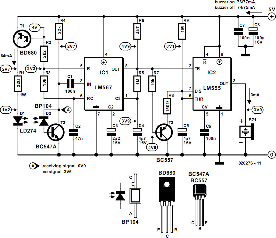
This circuit can be constructed using readily available, low-cost components, some of which may even be found in a junk box. The specified value of 22 for resistor R1 results in an average current of approximately 65 mA flowing...
As you can see, there is only one regulated 12 volt supply operating the entire circuit. This allowed me to adjust the offset within an operating window. By using a tantalum capacitor of reasonably high capacity, the signal passes...
The following circuit illustrates a Mains Remote-Alert Circuit Diagram. Features include simple circuitry, with the transmitted signal being conveyed effectively. The Mains Remote-Alert Circuit is designed to provide a notification system that alerts users about the status of mains power....
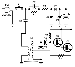
A simple proximity detector can be created using this electronic circuit. This circuit responds to the presence of a conductive object within a specific range. The sensitivity of the circuit can be adjusted with potentiometer P1 to achieve the...
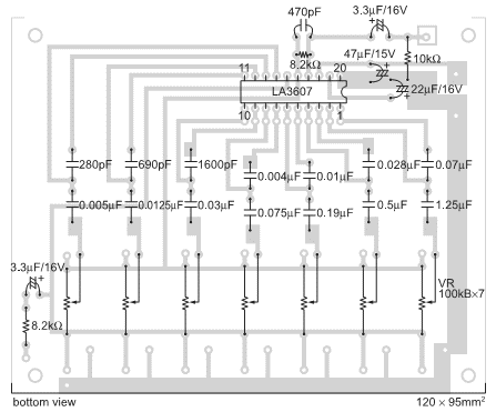
The integrated circuit LA3607 enables the configuration of a 7-band graphic equalizer for a single audio channel by incorporating additional capacitors and variable resistors. The cutoff frequency can be modified using variable resistors. It demonstrates high stability when handling...
This circuit functions to provide balanced, low distortion amplification and level shifting for wide bandwidth differential signals. It utilizes the LMH6552 integrated circuit (IC) along with resistors. The LMH6552 is a high-speed, low-distortion amplifier designed for differential signal processing. It...