
Camera Switch Circuit using 4017
This camera switch circuit provides a versatile solution for managing multiple camera feeds with a single monitor interface. The automatic mode, driven by a 555 timer in astable configuration, ensures that the switching between cameras occurs at a defined interval, dictated by the frequency of the square wave output. This frequency can be adjusted by altering the timing components of the 555 timer circuit, allowing for customization of the switching speed as per user requirements.
The 4017 decade counter is a key component in this design, as it sequentially activates the outputs corresponding to each camera. Each output is connected to a relay, which acts as a switch to connect the selected camera's output to the monitor. The use of transistors to drive these relays ensures that the circuit can handle the current required to energize the relays without overloading the counter.
In manual mode, the inclusion of switch SW2 allows the user to manually control which camera is displayed. This is particularly useful in scenarios where immediate switching is preferred over the automatic cycling. The logic transition triggered by SW2 directly affects the counter's output, providing a straightforward interface for the user.
The LED indicators are an essential feature, providing real-time feedback on which camera is currently active. This visual cue aids in monitoring operations, especially in multi-camera setups where confusion can easily arise.
For those implementing this circuit, attention should be paid to the power supply requirements, ensuring that the 4017 and other components receive the correct voltage to function optimally. The choice of resistors R3 to R7, while flexible, should be made to ensure proper current limiting for the LEDs and transistors, enhancing the reliability of the circuit.
Overall, this camera switch circuit is a practical and efficient solution for managing multiple camera inputs, suitable for various applications in surveillance, broadcasting, or event monitoring.Here is camera switch circuit. This circuit can be used for multiple cameras with one monitor. The circuit can be operated manually or automatically. When operated automatically the switch will be connected to the output of 555 astable multivibrator that will send a continous square wave in the 4017 counter. When counter is running, the 5 transi stor will switch one by one. For example; when Q1 is turned on the relay connected to Q1 will energized which will connect Out1 (Camera1) with the input (Monitor). If Q2 is turned on, Out2 (Camera2) will connect to input. For manual operation; each time the SW2 is push, transition will occur(Logic 0 to logic 1). That transition will change the output of the counter. Every time the SW2 is push, the counter output will change. LED`s are indicator to monitor which camera is connected to monitor. Pot1 is the adjustment for switching speed for the camera. The 4017 Power Supply is 5V. IC 74HC14, 10k trimmer and C4 form a Schmitt Trigger Circuit. R3-R7 can be 100 ohms to 330 ohms. It can also be omitted. For 4 Camera Operation. Cut the line from pin15-pin1; Connect Pin15 to Pin10. For 3 Camera Operation. Cut the line from pin15-pin1; Connect Pin15 to Pin7 We aim to transmit more information by carrying articles.
Please send us an E-mail to wanghuali@hqew. net within 15 days if we are involved in the problems of article content, copyright or other problems. We will delete it soon. 🔗 External reference
Related Circuits
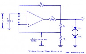
Non-sinusoidal waveform generators are also referred to as relaxation oscillators. The op-amp relaxation oscillator described is a square wave generator. Generally, square waves are relatively simple to produce. Similar to the UJT relaxation oscillator, the frequency of oscillation in...

The solar orientation circuit employs a comparator with window control to maintain engine idle as long as the two LDRs (light-dependent resistors) are exposed to equal illumination. In this scenario, half the supply voltage is applied to the non-inverting...
This circuit is designed to double nearly any DC input voltage while handling a substantial amount of current. For instance, it can work with input voltages ranging from 12 to 24V. With minor modifications, it can also provide any...
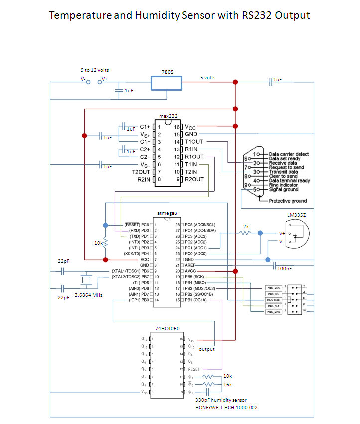
This is an affordable method for measuring temperature and humidity with a computer interface, designed as an entry-level project for high school students on a limited budget. The project involves the integration of a temperature and humidity sensor, such as...
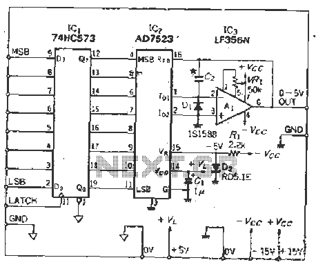
The IC latch is utilized to hold the digital data when the clock signal rises. The configuration includes a holding data port AD7s23, a thin film resistor ladder, and a switch that together form an 8-bit Digital-to-Analog Converter (DAC)....
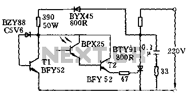
The circuit is designed to activate when the light intensity exceeds 700lx. In this configuration, a phototransistor and the BFY52 transistor are used to trigger the BTY91 thyristor with a current. When light strikes the phototransistor, a positive trigger...
Warning: include(partials/cookie-banner.php): Failed to open stream: Permission denied in /var/www/html/nextgr/view-circuit.php on line 713
Warning: include(): Failed opening 'partials/cookie-banner.php' for inclusion (include_path='.:/usr/share/php') in /var/www/html/nextgr/view-circuit.php on line 713