
Flashlight with Joule Thief

The circuit design centers around the joule thief, a simple boost converter that allows for the efficient use of low-voltage batteries. The joule thief circuit typically consists of a few key components: a transistor, a resistor, a toroidal inductor, and a diode. In this application, the transistor acts as a switch that rapidly turns on and off, creating a high-frequency oscillation that induces a higher voltage across the inductor.
The two AAA batteries provide a nominal voltage of 3.0 volts, which is suitable for powering the joule thief circuit. When the circuit is engaged, the joule thief will step up the voltage to a level sufficient to power the 5 mm white LED, which typically requires around 3.0 volts to function optimally. The LED will be connected in series with a current-limiting resistor to prevent excessive current flow that could damage the LED.
The design also considers the physical arrangement of components within the pen-style flashlight. The compact nature of the joule thief circuit allows it to fit within the existing housing, ensuring that the flashlight remains portable and easy to use. Additionally, the use of a white LED significantly enhances the brightness and efficiency compared to the original lamp, providing longer operational time from the same battery source.
Overall, this project exemplifies a practical application of electronic principles to create a more efficient and effective flashlight design, leveraging the capabilities of the joule thief circuit to maximize battery life and light output.This is probably the 1001 flashlight with a joule thief, but then again this is mine :) I used a pen style flashlight from duracell. It has a 2.2 volt lamp and two AAA batteries. One of the penlites is going to be replaced by the joule thief. And of course the lamp is being replaced by a 5 mm white LED. Thanks to all the great ideas on instructables to make this my first instructable. 🔗 External reference
Related Circuits
D1 (Schottky diode) and C2 form a rectifier to create DC voltage from the Joule Thief. A Zener diode D2 is included to limit the voltage to 5.1V, preventing damage to the microcontroller, which has a maximum voltage tolerance...
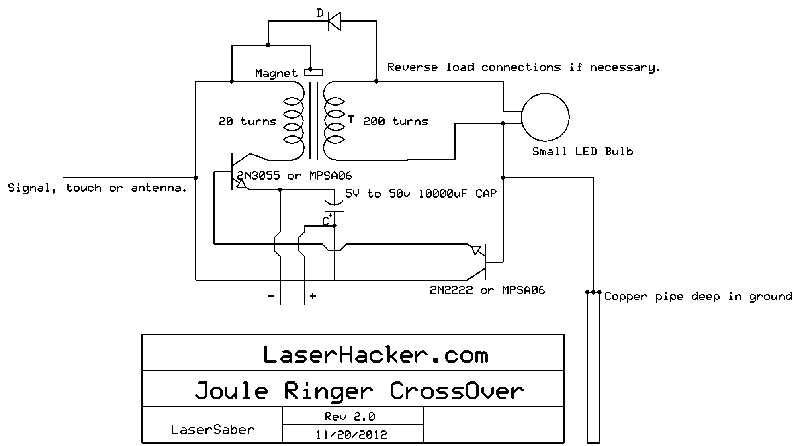
The conversion of a circuit from NPN to PNP configuration is in progress, along with a switch in polarity. Parts are being ordered for this modification. The conversion from an NPN to a PNP transistor involves several key changes in...
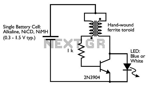
Drive a blue or white LED from a low voltage. Typically, lighting a blue or white LED requires a voltage of 3 to 3.5 V, which can be supplied by a 3 V lithium coin cell. However, a 1.5...
After spending more time with the circuit, the variable potentiometer yields more beneficial results than initially anticipated. The connection between the potentiometer position and LED brightness is established, but not with the transistor's on-time. This became clear after reviewing...
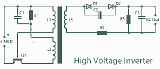
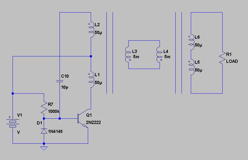
A 3V to 1000V inverter circuit has been constructed, but it is not functioning as intended. The creator seeks expert assistance to identify potential errors in the circuit design. Additionally, there is uncertainty regarding the transformer construction, as the...
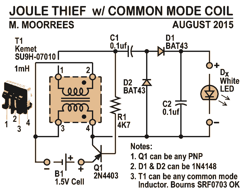
Like all joule thieves, this circuit boosts the voltage from a single 1.5V dry cell battery high enough to illuminate ultrabright GaN blue, green, or white LEDs. Instead of requiring a custom coil, it utilizes an off-the-shelf standard Kemet...