
joule thief circuit boosts voltage from 1.5V battery
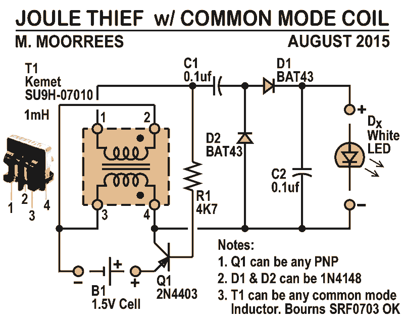
This joule thief circuit design effectively demonstrates the principles of voltage boosting while maximizing the efficiency of LED illumination. The use of the Kemet SU9H-07010 common mode choke simplifies the construction process, eliminating the need for custom coil winding. This component, combined with the PNP transistor, allows for operation at lower battery voltages, making the circuit versatile for various applications where battery life is critical.
The integration of a voltage doubler rectifier circuit is a notable enhancement, as it allows for the full utilization of the AC pulse generated by the joule thief. By employing Schottky diodes, specifically the BAT43, the circuit minimizes forward voltage drop, which is crucial for maximizing output voltage to the LEDs. The choice of BAT43 diodes over traditional silicon diodes ensures that the circuit can deliver optimal performance, particularly in low-voltage scenarios.
In summary, this joule thief circuit exemplifies an efficient and practical solution for powering ultrabright LEDs from low-voltage sources. The design's reliance on readily available components and its ability to operate at minimal battery voltages make it an attractive option for hobbyists and engineers alike, contributing to the development of sustainable and energy-efficient electronic devices.Like all joule thieves, it boost the voltage from a single 1.5V dry cell battery and boosts it high enough to light new ultrabright GaN, blue, green, or white LEDs. But instead of requiring a custom coil, it uses an off the shelf standard Kemet SU9H-07010 (1mH) common mode choke.
Joule thieves are very common circuits found on the web. Most are based around the blocking oscillator, which goes back to the tube days. The problem is that it requires a transformer, or at least a coil with a centertap. This often means winding your own around a ferrite or powdered iron toroid. But there still exist common two coil inductors used in modern circuits. Some added features, in addition to the coil choice: (1) a PNP transistor. With a silicon transistor, this circuit can run on a battery as low as 0.7V. Germanium transistors can even operate lower. As low as 0.25V. When germanium transistors were common, they more often than not came as PNP. NPN germanium transistors were harder to make. (2) a voltage doubler rectifier, and filter circuit has been added. Usually the LED is just placed across the pulsed output. This wastes half the signal. This doubler circuit, uses the whole AC pulse generated. To waste even less, BAT43 schottky diodes are used. Even though common 1N914/1N4148 diodes will work, the BAT43, will squeeze out another half volt. 🔗 External reference
Related Circuits
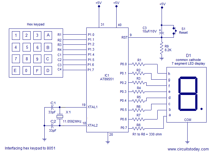
Interfacing a hex keypad to an 8051 microcontroller. The AT89S51 is utilized in this setup. A circuit diagram and assembly language program are included. A testing video is also provided. The interfacing of a hex keypad with the AT89S51 microcontroller...
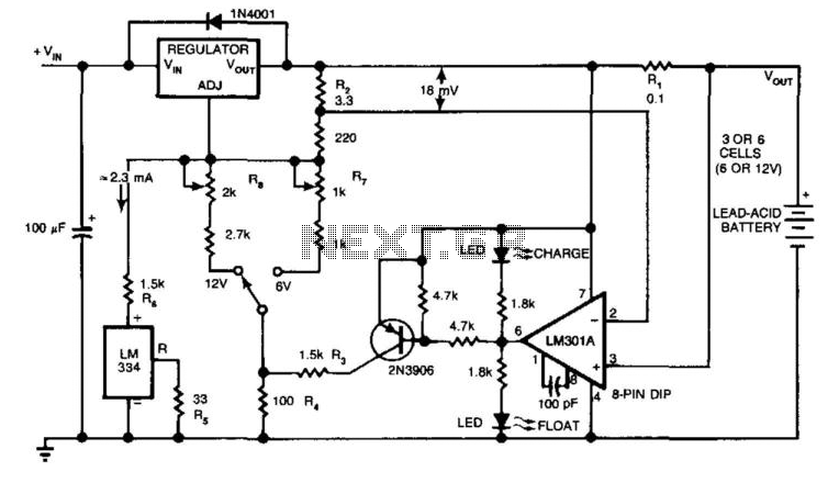
The circuit provides an initial charging voltage of 2.5 V per cell at 25°C to quickly charge a battery. The charging current decreases as the battery charges, and when the current falls to 180 mA, the charging circuit lowers...

The circuit is designed to switch off a specific lamp or a group of lamps based on varying ambient light levels. Once constructed, it will turn off a lamp at dawn and turn it on at dusk. The power...
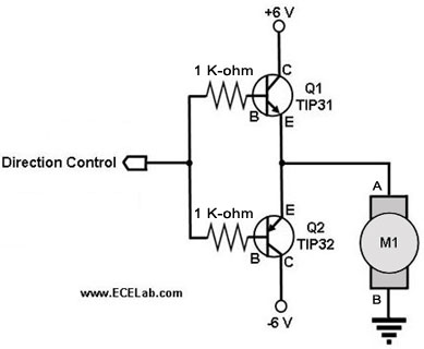
The following circuit illustrates a two-transistor DC motor driver circuit diagram. This circuit utilizes the TIP32 transistor. Features: operates in... The two-transistor DC motor driver circuit is designed to control the operation of a DC motor using two NPN transistors,...
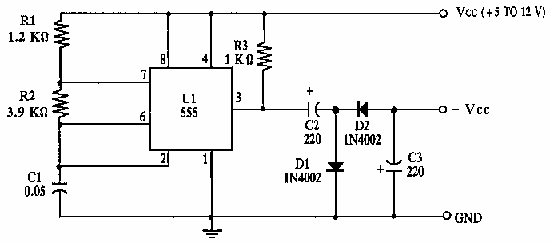
This circuit inverts the polarity of the input. Output is limited to less than 200mA. More: U1 NE555 timer IC R1 1.2k ohm resistor R2 3.9k ohm resistor R3 1k ohm resistor C1 0.05 uF ceramic capacitor C2, C3...
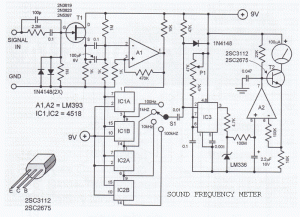
This sound frequency meter circuit is simple to build and can be constructed in a portable format. It can measure frequencies with a minimum level of 10 mV. The sound frequency meter circuit is designed to provide an effective and...