
joule thief circuit project
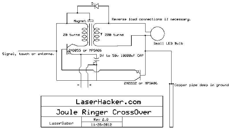
The conversion from an NPN to a PNP transistor involves several key changes in the circuit design. NPN transistors are configured to conduct current when a positive voltage is applied to the base relative to the emitter, while PNP transistors require a negative voltage for the same effect. This fundamental difference necessitates a re-evaluation of the biasing and connection of components within the circuit.
In a typical NPN circuit, the collector is connected to a positive voltage supply, and the emitter is grounded. During conversion to a PNP configuration, the collector must be connected to a negative voltage supply, and the emitter should be connected to the positive voltage. The base resistor values may also need to be adjusted to ensure proper biasing of the PNP transistor, which typically involves changing the resistor values to accommodate the new voltage levels.
Additionally, any other components that interact with the transistor, such as diodes or capacitors, may require reconfiguration to maintain the desired functionality. It is crucial to ensure that the signal flow remains consistent with the original design's intent, despite the polarity and transistor type changes.
When ordering parts, it is advisable to select PNP transistors with similar specifications to the original NPN components, including current rating, voltage rating, and frequency response, to ensure compatibility and performance. Proper attention to these details will facilitate a successful transition to the PNP configuration while maintaining circuit integrity.I convert this to PNP from NPN entirely + switch polarity I am ordering parts. 🔗 External reference
Related Circuits

A voltage-controlled oscillator (VCO) operates similarly to a voltage-to-frequency converter (VFC). Its output frequency is determined by a control voltage input. In the circuit diagram, 'd' represents the amplifier input voltage, which is set to 0.6V, while 'h' denotes...
This is a 25-watt basic power amplifier designed for ease of construction at a reasonable cost. It offers superior performance compared to standard STK module amplifiers commonly found in most mass-market stereo receivers produced today. The 25-watt basic power amplifier...
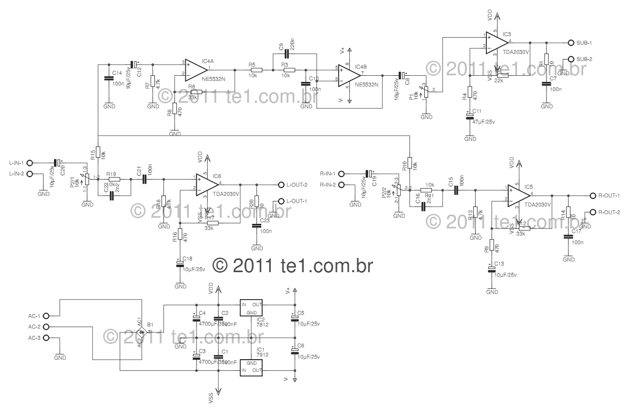
This circuit is a complete application for a 2.1 amplifier system, featuring two satellite speakers for TDA and one subwoofer. It is commonly used in commercial applications to enhance the audio output of computers using a stereo amplifier along...
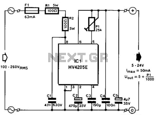
Direct derivation of 5 to 24 Vdc from AC mains without a transformer is possible with this circuit. Note that a direct mains connection to the DC output exists. Suitable safety precautions must be taken. This circuit design allows for...
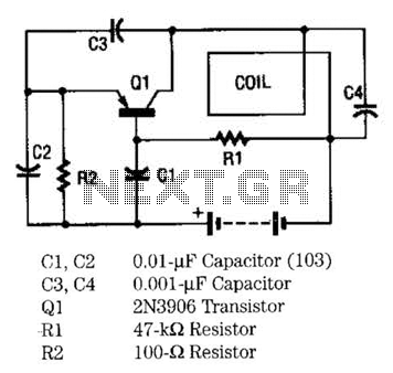
The metal locator utilizes a one-transistor oscillator in conjunction with an AM radio to detect metal. Transistor Q1 is a PNP transistor connected to the oscillator circuit. Resistor R1 supplies the appropriate base bias, while capacitors C3 and C4,...
With this circuit mounted in or near every phone in the house, it will allow users to know if the phone is being used and not to pick up the phone. When a phone is taken off hook, the...